90-823224--2 796
454 CID (7.4L) / 502 CID (8.2L) - 3A-49
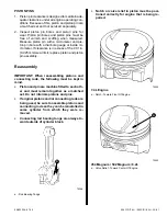
8. When all connecting rod bearings have been in-
stalled, tap each rod lightly (parallel to the crank-
pin) to make sure they have clearance.
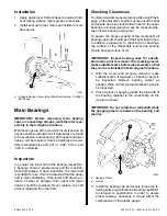
9. Measure all connecting rod side clearances (see
“Specifications”) between connecting rod caps
as shown.
72555
Connecting Rod/Piston
Assembly
Removal
1. Remove as outlined:
a. Oil pan and dipstick tube.
b. Baffle and oil pump.
c. Distributor and intake manifold.
d. Cylinder heads.
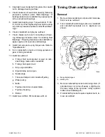
2. Use a ridge reamer to remove any ridge and/or
deposits from upper end of cylinder bore.
IMPORTANT: Before ridge and/or deposits are re-
moved, turn crankshaft until piston is at bottom
of stroke and place a cloth on top of piston to col-
lect cuttings. After ridge and/or deposits are re-
moved, turn crankshaft until piston is at top of
stroke, then remove cloth and cuttings.
3. Mark connecting rods and bearing caps (left bank
1, 3, 5 and 7; right bank 2, 4, 6 and 8 from front
to rear on same side as piston thrust).
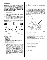
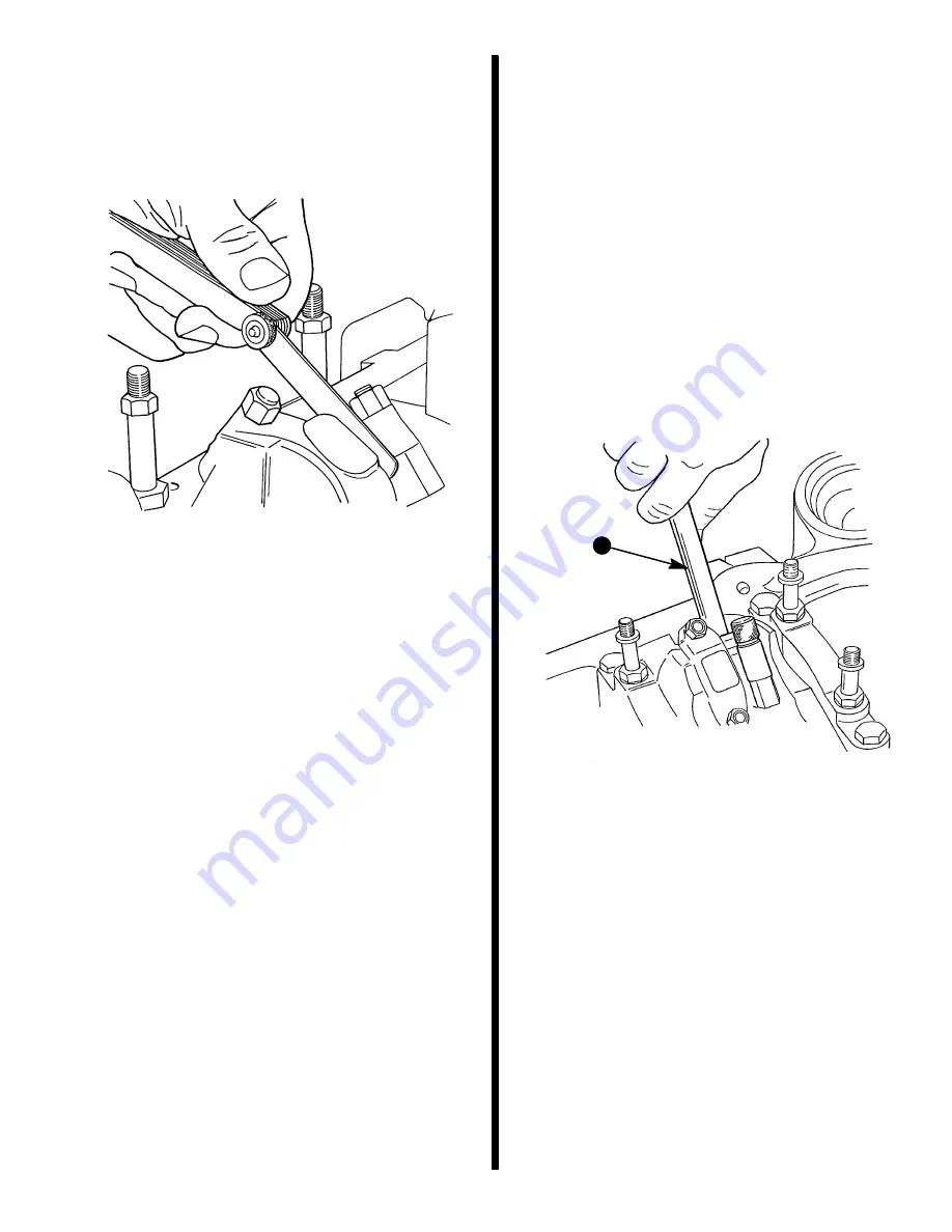
4. Remove connecting rod cap and install connect-
ing rod bolt guide (3/8-24 or 7/16-20) on bolts.
Push connecting rod and piston assembly out of
top of cylinder block.
NOTE:It will be necessary to turn crankshaft slightly
to disconnect and remove some connecting rod and
piston assemblies.
72572
a
a - Connecting Rod Bolt Guide 3/8-24 (J-5239) or 7/16-20
(J-35228)


