background image


200/225/250/275 VERADO 4-STROKE

90-10238051

Page  45 / 51


System Wiring Installation Checklist
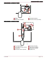
DATA CABLE

Verify the data harness is not routed near sharp edges, hot surfaces or moving parts.
Verify data harness is not routed near ignition components (coils, spark plug leads,

and spark plugs), high power VHF coax or radios.

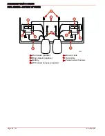
JUNCTION BOX (IF EQUIPPED)

Verify the data harness is not routed near sharp edges, hot surfaces or moving parts.
Ensure the harness connections are fastened within  25.4 cm (10 in.).
Verify that all unused receptacles are covered with a weather cap.

NON-MERCURY MARINE SUPPLIED IGNITION KEY SWITCH

If a non-Mercury Marine ignition key is used, verify that it passes the ingress protection

testing  per  IEC  IP66  specification  minimum.  Ignition  switches  must  pass  this

specification.

ELECTRONIC REMOTE CONTROL

Ensure Electronic Remote Control (ERC) connections are completed following ERC

installation instructions prior to engine operation.

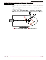
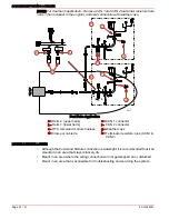
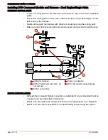
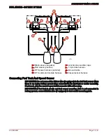
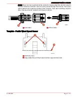
DTS COMMAND MODULE HARNESS

Verify that all connectors are properly inserted and locked in their receptacle (remote

control,  key  switch,  command  module,  lanyard  stop  switch  and  junction  box,  if

equipped).
Verify that while moving the remote control handle (full forward and full reverse) the

harness has unobstructed movement (moves freely).
Verify that the lanyard stop switch is wired into the system correctly.
Verify that the harness is fastened along the routing path.
Verify that all unused connectors have weather caps to prevent corrosion.
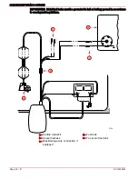
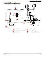
BATTERY

Verify that wing nuts have been replaced with hex nuts, provided.
Verify that all engine battery cables are connected to the correct terminals.
Verify that the DTS power harness leads are connected to the starting battery and

secured with locknuts.
Ensure the 5 Amp fuse for the DTS power harness is accessible.

LANYARD STOP SWITCH

Verify that the switch is installed.
Verify that the switch is connected to the DTS command module harness.

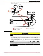
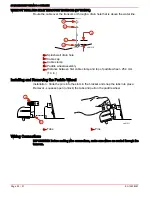
Propeller Installation

!

 WARNING

When installing or removing propeller, ensure the remote control is in neutral position

and the key switch is "OFF". Place a block of wood between the anti-cavitation plate

and propeller to prevent accidental starting and to protect hands from propeller blades

while removing or installing nut.

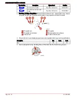
1. To aid in future removal of the propeller, liberally coat the propeller shaft splines with

one of the following Mercury/Quicksilver products:

Summary of Contents for 200 VERADO

Page 1: ...Hydraulic Hoses to the Power Steering Pump 14 Connection of the Hydraulic Hoses to the Steering Cylinder 15 Electrical Connections to the Steering Pump 17 Filling Power Steering System with Engine Not Running 19 Filling Power Steering System with Engine Running 21 Routing Connections Through the Cowl 22 Fuel Hose Connection 23 Wiring And Installation 24 Wire Color Code Abbreviations 24 Installatio...

Page 2: ...control do not splice or probe into any wire insulation of the DTS system Splicing or probing will damage the wire insulation allowing water to enter the wiring Water intrusion may lead to wiring failure and loss of throttle and shift control Accessory Electric Fuel Pump Fuel Line Primer Bulb IMPORTANT Do not install either an accessory electric fuel pump or a fuel line primer bulb into the fuel s...

Page 3: ... Precision or Quicksilver Accessories have been specifically designed and tested for this outboard Some accessories not manufactured or sold by Mercury Marine are not designed to be safely used with this outboard or outboard operating system Acquire and read the installation operation and maintenance manuals for all selected accessories Fuel Tanks Portable Fuel Tank Select a suitable location in t...

Page 4: ...ight from a point on the pedestal 48 mm 1 7 8 in above center of top mounting hole to the bottom of the boat transom For heights over 56 0 cm 22 in a propeller designed for surfacing operation is usually preferred f Maximum boat speed m p h anticipated NOTICE The static waterline with boat at rest must be below the MAX STATIC WATERLINE mark on the idle relief grommet located at the rear of the out...

Page 5: ...pecifications a b a 4241 a Minimum transom opening b Engine center line for dual engine 66 0 cm 26 in Minimum Transom Opening Single engine 99 0 cm 39 in Dual engine 165 0 cm 65 in Maximum Outboard Mounting Height The mounting height of the outboard must not exceed 63 5 cm 25 in for L models 76 2 cm 30 in for XL models and 88 9 cm 35 in for XXL models Mounting the outboard higher may cause damage ...

Page 6: ...rd Mounting Holes IMPORTANT Before drilling any mounting holes carefully read Determining Recommended Outboard Mounting Height There is a 19 mm 0 75 in difference between the outboard mounting holes in the transom brackets WARNING Avoid possible serious injury or death Do not under any circumstances allow the upper outboard mounting bolts to be closer than 25 4 mm 1 in from the top of the boat tra...

Page 7: ...m drilling fixture drill four 13 mm 17 32 in holes perpendicular to and through the transom Lifting Outboard 1 Remove top cowl and engine flywheel cover 2 Install lifting ring flywheel puller to flywheel Tighten bolts securely 3 Lift engine using engine lift with a minimum capacity of 450kg 1000 lb 4 Avoid interference by placing the lower mounting bolts into the lower mounting slots before placin...

Page 8: ...ting Eye 91 895343T01 6 Fasten outboard with mounting hardware provided Refer to Fastening Outboard Fastening Outboard 1 Place lower mounting bolts into mounting slots before placing outboard on transom 2 Refer to Determining Recommended Outboard Mounting Height and install outboard to the nearest recommended mounting height 3 Fasten outboard with the stainless steel bolts nylon insert locknuts an...

Page 9: ... sealer apply to shank of bolts not threads Outboard Transom Mounting Hardware Supplied with Outboard Part Number Part Name Description 10 67755003 Transom bolt 1 2 x 20 x 5 50 in long 3 25 in thread 11 826711 17 Nylon insert locknut 1 2 x 20 12 28421 Washer inner 0 516 in ID x 1 50 in OD 12 895062 Washer outer 0 551 in ID x 1 06 in OD Available Transom Mounting Bolts Part Number Part Name Descrip...

Page 10: ...e extreme maneuvers If this happens and steering performance is deemed unacceptable for the application a second accessory cylinder may be rigged When using a second steering cylinder the 40cc helm should be replaced with a 50cc helm SELECTING LOCATION FOR THE POWER STEERING PUMP CAUTION To ensure proper steering operation hydraulic power steering system must be protected from contamination Make h...

Page 11: ...each of the auxiliary battery Pump should be mounted in an area that allows sound enclosure cover removal and easy access to the fill cap Install pump in an area where bilge water will not contaminate the pump To reduce transmitted noise mount pump on wood or fiberglass surface Avoid mounting pump on aluminum or steel surfaces REQUIRED MOUNTING CLEARANCES FOR THE POWER STEERING PUMP a c ob01458 b ...

Page 12: ...t be routed up through steering helm opening in dash and secured to helm fittings prior to mounting the steering helm 1 Place the steering hoses through one backing plate on the internal side of the dashboard Route the steering hoses through the drilled opening and place the required amount of backing plates on the hoses on the external side of the dashboard NOTE The number of backing plates varie...

Page 13: ...gs from turning while tightening hoses Do not over tighten the hose connections a P T ob01461 R STAR L PORT b c d e a Thin wrench b Helm hex fitting wrench size P T 19 mm 3 4 in c Helm hex fitting wrench size R L 16 mm 5 8 in d Hydraulic hose hex fitting wrench size P T 21 mm 13 16 in e Hydraulic hose hex fitting wrench size R STAR L PORT 18 mm 11 16 in Helm Fitting ID Mark Hose ID Mark Descriptio...

Page 14: ...es to the Power Steering Pump 1 Remove and discard the yellow protector cap from end of tank low pressure fitting 2 Connect the low pressure hydraulic hose from the steering helm to the low pressure fitting on the pump reservoir as shown Fasten hose to fitting with constant tension spring clamp b c ob01462 a a Yellow protector cap remove and discard b Low pressure hydraulic hose from steering helm...

Page 15: ...ering Cylinder 1 Route the hydraulic hoses to the outboard steering cylinder Bulkhead fittings are available if an opening does not exist in the engine well a b ob01464 a Bulkhead fitting bulkhead thickness up to 1 9 cm 0 75 in 22 892517 b Bulkhead fitting bulkhead thickness up to 7 62 cm 3 in 22 892518 NOTE The 90 hose fittings on the steering cylinder can be rotated to align with hose routing St...

Page 16: ...tion fittings b 90 fitting c Straight fitting 3 Remove and discard the shipping caps from the two fittings on the steering cylinder Ensure O ring seals did not lift off with shipping caps 4 Ensure O ring seals are in place on end of each fitting a a ob01466 a O rings 5 Make the hydraulic steering hose connections to the steering cylinder as shown ob01467 L PORT R STAR a b a Port fitting L PORT b S...

Page 17: ... should be connected directly to the outboard starting battery a b c d e f g h i j k 4250 b Single Engine Application a Engine b Battery cable c DTS power harness d Battery e Power steering fuse 90 Amp f Power steering pump 12V positive harness g Power steering pump h Driver module i Power steering pump ground harness j Power steering signal harness k Engine signal harness ...

Page 18: ... drawn from the starting battery with the highest state of charge a b c d e f g h i j m l m 4154 k k Dual Engine Application a Port engine b Starboard engine c Port battery d Starboard battery e Automatic Power Switch APS f Power Steering Pump g Power steering pump 12V positive harness h Power steering pump ground harness i Driver module j Dual engine power steering adaptor k DTS power harness l P...

Page 19: ...fluid should then be drained and replaced with SAE 0W 30 Full Synthetic Power Steering Fluid as soon as possible to avoid loss of performance in power steering system Fluid Type Capacity Mercury Part Number SAE 0W 30 Full Synthetic Power Steering Fluid 1 2 liters 1 2 quarts depending on length of steering hoses 92 858002K01 1 Disconnect power steering signal harness from engine signal harness 2 Co...

Page 20: ...wer steering primer module and refill the pump tank Repeat this operation until pump tank stays full 6 Power up and activate the pump while slowly turning the steering wheel towards the full lock position in one direction Carefully monitor the fluid level until fluid drops halfway stop turning the steering wheel and refill the pump tank Repeat this operation turning the steering wheel from full lo...

Page 21: ...eceding 13 Turn off both switches remove the power steering primer module and reconnect the power steering signal harness from the engine to the pump Filling Power Steering System with Engine Running 1 Remove the filler cap and filter from the power steering pump 2 Fill the pump tank with recommended power steering fluid 4101 a b c a Cap b Filter c Full level 3 Start and run the engine until the s...

Page 22: ...ring cylinder 8 Turn the steering wheel to opposite full lock position and repeat procedure for bleeding steering system 9 Replace the filter and filler cap on the power steering pump 10 If desired the power steering system can be rechecked after sitting overnight to remove any air that may possibly be left in the system Repeat steps for bleeding steering system preceding Routing Connections Throu...

Page 23: ...harness d DTS power harness vessel sensor harness power steering pump harness e Large diameter battery cables f Small diameter battery cables g Grommet fitting h Front cowl opening 2 Insert rubber grommet into fitting and secure fitting in front cowl opening Fuel Hose Connection FUEL HOSE SIZE IMPORTANT Fuel line inside diameter I D must be 10 mm 3 8 in with separate fuel line fuel tank pickup for...

Page 24: ...trol CONNECTORS IMPORTANT Connectors should never have to be forced into the receptacle Ensure that connectors are free of any lubricant or dielectric grease before installation When the connector is properly aligned it will only take a small amount of pressure to insert it into the receptacle Rotate the locking collar to secure the electrical connection NOTE Connect only one data harness of the r...

Page 25: ...f Equipped Although the junction box connections are watertight it is recommended that the junction box be mounted in an area that stays relatively dry Mount in an area where the wiring connection will not get stepped on or disturbed Mount in an area that is accessible for troubleshooting and servicing the system Ensure the DTS command module harness will reach all the connection points Fasten all...

Page 26: ...y Switch a Connector Packard Metripack 150 Series Sealed 6 pin b Ignition switch c Crank d 12V e Lanyard stop f Ground g Run h Accessory 4 position key switch Wiring Accessories NOTE Refer to Mercury Precision Parts Accessories Guide System Wiring Reference Points FEATURES DTS power harness Provides 12V power to the DTS system Requires connection to the starting battery If starting battery is loca...

Page 27: ...ower harness f 5 Amp fuse Battery Cable Size For Outboard Models IMPORTANT Only use copper battery cables Do not use aluminum cables for any outboard marine installations If longer battery cables are required the wire gauge size must increase See chart following for correct wire gauge size DTS L models are equipped with 3 7 m 12 ft cables DTS XL and XXL models are not shipped with battery cables a...

Page 28: ...2 2 5 5 m 18 ft 4 2 2 2 5 8 m 19 ft 4 2 2 2 6 1 m 20 ft 4 2 2 2 6 4 m 21 ft 2 1 2 1 6 7 m 22 ft 2 1 2 1 7 0 m 23 ft 2 1 2 1 7 3 m 24 ft 2 1 2 1 7 6 m 25 ft 2 1 2 1 7 9 m 26 ft 2 1 0 1 1 0 8 2 m 27 ft 2 1 0 1 1 0 8 5 m 28 ft 2 1 0 1 1 0 8 8 m 29 ft 2 1 0 1 1 0 9 1 m 30 ft 2 1 0 1 1 0 9 4 m 31 ft 2 1 0 1 1 0 9 8 m 32 ft 2 1 0 1 1 0 10 1 m 33 ft 2 2 0 1 0 2 0 10 4 m 34 ft 2 2 0 1 0 2 0 10 7 m 35 ft 1...

Page 29: ... Engine SINGLE HELM IMPORTANT Avoid sharp bends in the harness Minimum bend radius should be 7 6 cm 3 in a b 3619 a 14 pin data harness b Clamp or cable tie DUAL HELM 3682 a b c d e a 14 pin data harness b Helm 2 upper helm c Helm 1 lower helm d Dual helm adapter Y harness e Clamp or cable tie ...

Page 30: ...ngine SINGLE HELM IMPORTANT Avoid sharp bends in the harness Minimum bend radius should be 7 6 cm 3 in 3977 a b a 14 pin data harness b Clamp or cable tie DUAL HELM 3978 a b c d e c a Helm 2 upper helm b Helm 1 lower helm c 14 pin data harness d Dual helm adapter Y harness e Clamp or cable tie ...

Page 31: ... reach their installation points Inspect the routing path to make sure surfaces are free of any sharp edges or burrs that could cut the harness Fasten and support the harness with clamps or cable ties along the routing path Make sure all connections are tight and seal all unused connectors with weather caps 3622 a b Single Helm Application a DTS command module harness b Clamp or cable tie ...

Page 32: ... a Helm 2 upper helm b Helm 1 lower helm c DTS command module harness d Clamp or cable tie e CAN 1 connector f CAN 2 connector g Weather caps h Terminator resistors blue CAN1 CAN2 MODULE INSTALLATION Although the Command Module connection is watertight it is recommended that it be mounted in an area that stays relatively dry Mount in an area where the wiring connection will not get stepped on or d...

Page 33: ...ted to the command module will reach all the connection points a b 3625 Single Helm Application a DTS command module b Clamp or cable tie 3678 a b c d e f Dual Helm Application a Helm 2 b Helm 1 c DTS command module d Clamp or cable tie e Terminator resistors blue CAN1 CAN2 f Weather caps ...

Page 34: ...g path Make sure all connections are tight and seal all unused connectors with weather caps Terminator CAN 1 Terminator CAN 1 Terminator CAN 2 Terminator CAN 2 a b d 3689 c c e a CAN link harness b CAN 2 Terminator resistors do not remove c CAN 1 connectors d Clamp or cable tie e DTS command module harness MODULE INSTALLATION Although the Command Module connection is watertight it is recommended t...

Page 35: ...be used to secure battery leads to battery posts to avoid loss of electrical power Do not use deep cycle batteries Engines must use a marine starting battery with 1000 MCA 800 CCA or 180 Ah When connecting engine battery hex nuts must be used to secure battery leads to battery posts Torque nuts to specification Description Nm lb in lb ft Hex nuts 13 5 120 IMPORTANT Battery cable size and length is...

Page 36: ...er to engine installation manual for size requirements DO NOT USE WING NUTS DO NOT USE DEEP CYCLE BATTERIES 13 5Nm 120 lbs in DTS Digital Throttle and Shift applications and Optimax engines must use a marine starting battery with 1000 MCA 800 CCA or 180 Ah rating 3486 Connecting Battery Cables and DTS Power Harness CAUTION To avoid the possibility of loss of electrical power due to the DTS power h...

Page 37: ...ry b Black sleeve negative c Red sleeve positive d DTS power harness provided SINGLE ENGINE BATTERY AT HELM a b e 3699 d c f g h a 14 pin data harness b DTS command module harness c Junction box d DTS power harness optional e Red sleeve Positive f Black sleeve Negative g Vessel sensor harness h Weather caps ...

Page 38: ...4 STROKE Page 38 51 90 10238051 DUAL ENGINE BATTERY AT STERN c b c a b a 3680 d d e f g a Red sleeve positive b Black sleeve negative c Battery d DTS power harness provided e Ground cable f Data cable g Vessel sensor harness ...

Page 39: ...ound cable h Vessel sensor harness Connecting Fuel Tank And Speed Sensor IMPORTANT Do not connect the blk orn wire if equipped to the fuel tank sensor when there is an engine battery ground strap connected to the fuel tank or sender assembly If not used plug the unused open bullet connector with rubber plug IMPORTANT If fuel tank is plastic and fuel sensor mounting plate is not connected to batter...

Page 40: ...e grounded to hull or battery ground in accordance to coast guard regulations BLK BLU WHT YEL BLK ORG PUR YEL GRY BLU TAN ORG BLK O RG LT BLU BLK PNK BLK BLK ORG b c d e a 5759 a Paddle wheel kit b Vessel harness c Black orange wire connection if equipped d Fuel tank e To second fuel tank ...

Page 41: ...38051 Page 41 51 Switched 12V Accessory Connection ob01495 PUR RED a b c d e f g h a Battery b Fuse 40 Amp c Power harness with 40 Amp fuse d Switched 12V e Complete kit f Terminal block g Accessory power relay h DTS Command Module harness ...

Page 42: ...L GRN YEL GRN ORG GRN RED BLK YEL BLK YEL BLK BLK OFF O N e f g h i j d a Start stop switch optional b SmartCraft System View optional c SmartCraft Link Gauge optional d GPS connection e Displace harness f Cable adaptor male to female g Weather caps h Junction box optional i Accessory power relay optional j Foot throttle optional ...

Page 43: ...YEL GRN ORG GRN RED BLK YEL BLK YEL BLK BLK OFF O N d e f g h i j a Start stop switch optional b SmartCraft System View optional c SmartCraft Link Gauge optional d GPS connection e Display harness f Cable adaptor male to female g Weather caps h Junction box i Accessory power relay optional j Foot throttle optional ...

Page 44: ...stor c DTS Command Module d Junction box connection optional e Connector Zero Effort controls f Horn g Accessory power relay optional h DTS Command Module harness i Clamp j Connector stop start switch optional k Remote control connections l Key switch m Remote control n To port engine o Lanyard stop switch p To starboard engine q System View optional r To starboard engine s CAN link harness ...

Page 45: ...lanyard stop switch and junction box if equipped Verify that while moving the remote control handle full forward and full reverse the harness has unobstructed movement moves freely Verify that the lanyard stop switch is wired into the system correctly Verify that the harness is fastened along the routing path Verify that all unused connectors have weather caps to prevent corrosion BATTERY Verify t...

Page 46: ...all forward thrust hub replaceable drive sleeve propeller thrust hub propeller nut retainer and propeller nut onto the shaft b c a d f e ob00421 a Propeller nut b Propeller nut retainer c Thrust hub d Propeller e Replaceable drive sleeve f Forward thrust hub 3 Place a block of wood between gearcase and propeller and torque nut to specification Description Nm lb in lb ft Nut 75 55 4 Secure propelle...

Page 47: ...transom where the propeller blade is rotating downward Usually the right starboard side to minimize cavitation If feasible mount at least 50 mm 2 in beyond the swing radius of the propeller Dual engine installation Mount the paddle wheel between the engines as close to the center line keel of the boat as possible On slower heavier displacement boats however positioning it farther from the keel is ...

Page 48: ...template is aligned with the transom bottom edge as shown NOTE The mounting template provided is located on the last page of this instruction sheet 2 Using a 28 or 9 64 in bit drill two 22 mm 7 8 in deep holes where indicated on the template To prevent drilling too deeply wrap masking tape around the drill bit 22 mm 7 8 in from the point end of drill bit NOTE In fiberglass hulls first chamfer the ...

Page 49: ...ontrols 2 Drill a 15 mm 5 8 in diameter hole 3 Route the cable through the drilled hole Seal the transom hole with silicone RTV or a comparable marine sealer after the cable has been routed through NOTE The hole for the first clamp should be 25 mm 1 in above the paddle wheel The hole for the second clamp should be positioned halfway between the first clamp and the cap covering the transom hole dri...

Page 50: ...p c Cable clamp d Paddle wheel assembly e Distance between first cable clamp and top of paddle wheel 25 4 mm 1 0 in Installing and Removing the Paddle Wheel Installation Slide the pins into the slots in the bracket and snap the tabs into place Removal squeeze open unlock the tabs and pull on the paddle wheel a b ob01511 a Tabs b Pins Wiring Connections IMPORTANT Before making wire connections make...

Page 51: ...rough the transom Push each wire terminal into its respective location in the connector Push wire in until they snap into place Secure wires into connector with the wire retainer A A B B C C D D A A B B C C D D a b b WHT YEL BLU BLK ob01512 a Connector b Wire retainer Template Paddle Wheel Speed Sensor a b ob01513 a Drill holes here b Align dotted line with the transom bottom edge and fold under ...

Reviews: