


MAINTENANCE
106
5. To remove minor scratches, use Mercury Marine Cowl
Finishing Compound (92-859026K 1).
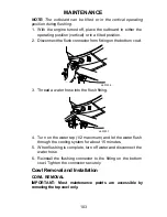
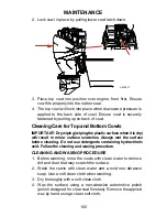
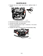
Cleaning Care for the Powerhead (Saltwater Use)
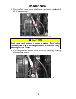
If the outboard is operated in saltwater, remove the top cowl and
flywheel cover. Inspect the powerhead and powerhead
components for salt build-up. Wash off any salt build-up from the
powerhead and powerhead components with fresh water. Keep
water spray out of the air filter/intake and alternator. After washing,
allow the powerhead and components to dry. Apply Quicksilver or
Mercury Precision Lubricants Corrosion Guard spray on the
external metal surfaces of the powerhead and powerhead
components. Do not allow the Corrosion Guard spray to come in
contact with the alternator drive belt, belt pulleys or the outboard
motor mounts.
IMPORTANT: Do not allow lubricant or Corrosion Guard spray to
come in contact with the alternator drive belt or the belt pulleys.
The alternator drive belt could slip and be damaged if it becomes
coated with any lubricant or Corrosion Guard spray.
Tube Ref No.
Description
Where Used
Part No.
120
Corrosion Guard
External metal
surfaces of the
powerhead and
powerhead
components.
92-802878-55
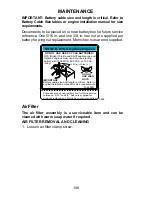
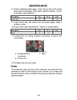
Battery Inspection
The battery should be inspected at periodic intervals to ensure
proper engine starting capability.
IMPORTANT: Read the safety and maintenance instructions
which accompany your battery.
1. Turn off the engine before servicing the battery.
2. Add water as necessary to keep the battery full.
3. Make sure the battery is secure against movement.
4. Battery cable terminals should be clean, tight, and correctly
installed. Positive to positive and negative to negative.
Summary of Contents for 200 VERADO
Page 4: ...iv ...


