background image


600.101/102UK User Manual


OPERATING INSTRUCTIONS 
DC & AC VOLTAGE MEASUREMENT 

1.


Connect red test lead to “VΩmA” jack, Black lead to 
“COM” jack.


2.


Set RANGE switch to desired VOLTAGE position, if the 

voltage to be measured is not known beforehand, set 
switch to the highest range and reduce it until 

satisfactory reading is obtained. 

3.


Connect test leads to device or circuit being 

measured. 

4.


Turn on power of the device or circuit being measured 

voltage value will appear on Digital Display along with 

the voltage polarity. 


DC CURRENT MEASUREMENT 

1.


Red lead to “VΩmA”. Black lead to “COM” (for 

measurements between 200mA and 5A connect red 

lead to “

5

A” jack with fully depressed.)


2.


Set RANGE switch to desired DCA position. 

3.


Open the circuit to be measured, and connect test 
leads in SERIES with the load in with current is to 

measure. 

4.


Read current value on Digital Display. 

5.


Additionally, “

5

A” function is designed for intermittent 

use only. Maximum contact time of the test leads with 
the circuit is 10 seconds, with a minimum intermission 

time of 15 minutes between tests. 


RESISTANCE MEASUREMENT 

1.


Red lead to “VΩmA”. Black lead to “COM”.


2.


Set RANGE switch to desired 

Ω

 position. 

Summary of Contents for 600.101UK

Page 1: ...Please read this manual thoroughly and ensure all contents are fully understood before use of the apparatus WARNING MTB01 MTB02 Digital Multimeter Item Ref 600 101UK 600 102UK...

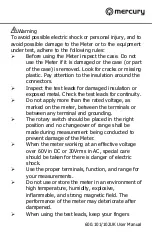
Page 2: ...re than the rated voltage as marked on the meter between the terminals or between any terminal and grounding The rotary switch should be placed in the right position and no changeover of range shall b...

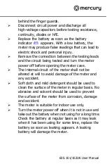
Page 3: ...ning the meter case The internal circuit of the meter shall not be altered at will to avoid damage of the meter and any accident Soft cloth and mild detergent should be used to clean the surface of th...

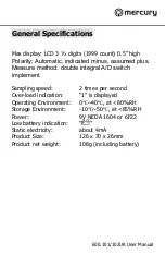
Page 4: ...Measure method double integral A D switch implement Sampling speed 2 times per second Over load indication 1 is displayed Operating Environment 0 40 at 80 RH Storage Environment 10 50 at 85 RH Power 9...

Page 5: ...600 101 102UK User Manual COM jack V mA jack 10A jack hFE socket LCD RANGE switch...

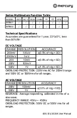
Page 6: ...ION ACCURACY 200mV 100uV 0 5 of rdg 3D 2000mV 1mV 20V 10mV 200V 100mV 500V 1V 1 0 of rdg 5D 0 8 of rdg 5D OVERLOAD PROTECTION 220V rms AC for 200mV range and 500V DC or 500Vrms for all ranges AC VOLTA...

Page 7: ...E RESOLUTION ACCURACY 200uA 100nA 2000uA 1uA 20mA 10uA 200mA 100uA 2 0 of rdg 2D 5A 10mA 2 0 of rdg 10D 1 8 of rdg 2D OVERLOAD PROTECTION F0 5A 250V and F5A 250V fuse MEASURING VOLTAGE DROP 200mV RESI...

Page 8: ...splay along with the voltage polarity DC CURRENT MEASUREMENT 1 Red lead to V mA Black lead to COM for measurements between 200mA and 5A connect red lead to 5A jack with fully depressed 2 Set RANGE swi...

Page 9: ...he forward voltage drop in mV will be displayed If the diode is reversed figure 1 will be shown TRANSISTOR hFE MEASUREMENT 1 Set RANGE switch to the hFE position 2 Determine whether the transistor is...

Page 10: ...he old and replace with a new one Be careful to observe polarity ACCESSORIES Operator s instruction manual Set of test leads red and black 9 volt battery NEDA 1604 6F22 type EN61010 1 2010 This produc...

Reviews: