background image

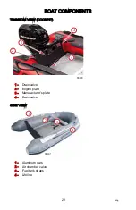
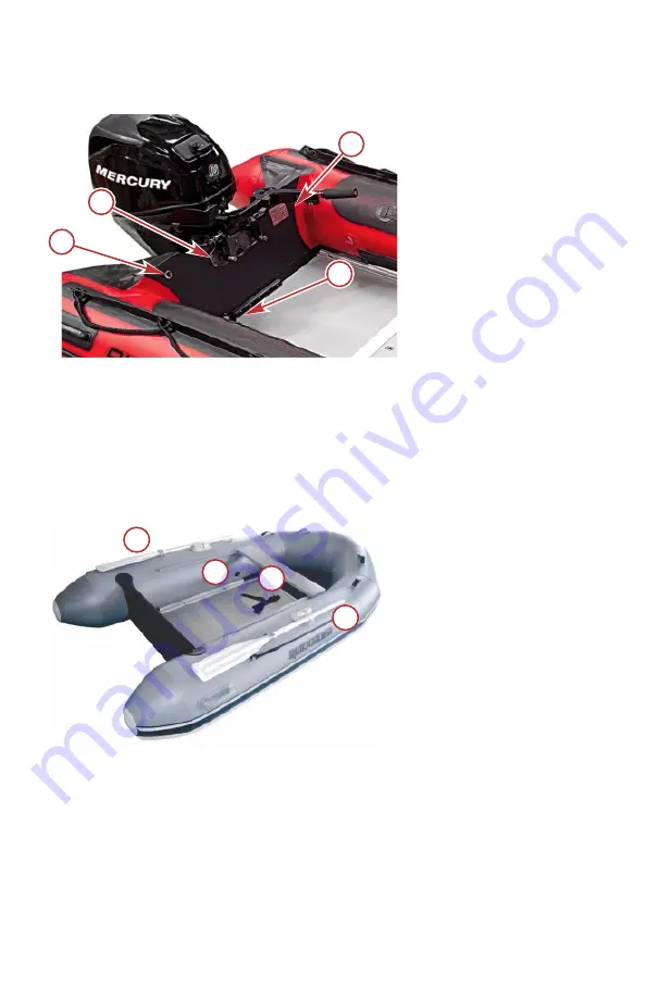
TRANSOM VIEW (COCKPIT)

1 -

Drain valve

2 -

Engine plate

3 -

Manufacturer's plate

4 -

Drain valve

SIDE VIEW

1 -

Aluminum oars

2 -

Air chamber valve

3 -

Fuel tank straps

4 -

Lifeline

66429

1

2

3

4

1

2

3

4

66431

BOAT COMPONENTS


22

eng

Summary of Contents for Quicksilver 200 Tendy Slatted

Page 1: ...Quicksilver Inflatables 2018 Mercury Marine Quicksilver Inflatables 8M0145401 318 eng ...

Page 2: ...eng ...

Page 3: ... a new CE directive specifies HIN hull identification number will be replaced with WIN watercraft identification number HIN hull identification number is used primarily within the North American continent Warranty Message The product you have purchased comes with a limited warranty from Mercury Marine The terms of the warranty are set forth in the Warranty Information section of this manual The wa...

Page 4: ...us Bravo One Bravo Two Bravo Three Circle M with Waves Logo K planes Mariner MerCathode MerCruiser Mercury Mercury with Waves Logo Mercury Marine Mercury Precision Parts Mercury Propellers Mercury Racing MotorGuide OptiMax Quicksilver SeaCore Skyhook SmartCraft Sport Jet Verado VesselView Zero Effort Zeus 1 On the Water and We re Driven to Win are registered trademarks of Brunswick Corporation Pro...

Page 5: ...ibilities 5 Before Operating Your Boat 5 Lanyard Stop Switch 5 Protecting People in the Water 8 Wave and Wake Jumping 8 Impact with Underwater Hazards 9 Exhaust Emissions 10 Safe Boating Suggestions 11 Unaided Reboarding 12 Quicksilver Inflatable Specifications 13 Manufacturer s Capacity Plate 19 Declaration Of Conformity 20 Boat Components Component Location 21 Transporting Trailering Boat 23 eng...

Page 6: ... Plug Drain Valve Operation 36 Inflation of Tube 37 How to Inflate Your Quicksilver Boat 38 Outboard Power 39 Preoperating Check List 39 Loading 40 Towing 41 Air Chamber Deflates Accidentally 41 Beaching 42 Davits 42 Maintenance Refueling 43 Cleaning Procedure 43 Deflating 44 Folding Instructions 45 Air Leak 46 Repairs Air Chamber Repair Hypalon Fabric 48 Air Chamber Repair PVC Fabric 49 Storage S...

Page 7: ...Owner Service Assistance Local Repair Service 52 Service Away from Home 52 Parts and Accessories Inquiries 52 Service Assistance 52 Ordering Literature 54 eng v ...

Page 8: ...eng vi ...

Page 9: ... of the product There is no charge for this service For products purchased outside the United States and Canada contact the distributor in your country or the Marine Power Service Center closest to you Warranty Registration United States and Canada To be eligible for warranty coverage the product must be registered with Mercury Marine At the time of sale the selling dealer should complete the warr...

Page 10: ...s oar locks oars rope air pump lifting handles d rings oar holders valves seat webbings and transom integrity are covered by this Limited Warranty for two 2 years from the date the product is first sold or the date on which the product is first put into service whichever occurs first The repair replacement of parts or the performance of service under this warranty does not extend the life of this ...

Page 11: ... expenses associated with that service The purchaser shall not unless requested by Mercury Marine ship the product or parts of the product directly to Mercury Marine Proof of registered ownership must be presented to the dealer at the time warranty service is requested to obtain coverage WHAT IS NOT COVERED This Limited Warranty does not cover routine maintenance items adjustments normal wear and ...

Page 12: ... TO THE LIFE OF THE EXPRESS WARRANTY INCIDENTAL AND CONSEQUENTIAL DAMAGES ARE EXCLUDED FROM COVERAGE UNDER THIS WARRANTY SOME STATES COUNTRIES DO NOT ALLOW FOR THE DISCLAIMERS LIMITATIONS AND EXCLUSIONS IDENTIFIED ABOVE AS A RESULT THEY MAY NOT APPLY TO YOU THIS WARRANTY GIVES YOU SPECIFIC LEGAL RIGHTS AND YOU MAY ALSO HAVE OTHER LEGAL RIGHTS WHICH VARY FROM STATE TO STATE AND COUNTRY TO COUNTRY W...

Page 13: ... your attention to special safety instructions that should be followed WARNING Indicates a hazardous situation which if not avoided could result in death or serious injury CAUTION Indicates a hazardous situation which if not avoided could result in minor or moderate injury NOTICE Indicates a situation which if not avoided could result in engine or major component failure Lanyard Stop Switch The pu...

Page 14: ...d stop switch is to stop the engine when the operator moves far enough away from the operator s position to activate the switch This would occur if the operator accidentally falls overboard or moves within the boat a sufficient distance from the operator s position Falling overboard and accidental ejections are more likely to occur in certain types of boats such as low sided inflatables bass boats...

Page 15: ... the operator s station without first disconnecting the stop switch lanyard from the operator Accidental or unintended activation of the switch during normal operation is also a possibility This could cause any or all of the following potentially hazardous situations Occupants could be thrown forward due to unexpected loss of forward motion a particular concern for passengers in the front of the b...

Page 16: ...al propeller rotation can cause serious injury WHILE THE BOAT IS STATIONARY WARNING A spinning propeller a moving boat or any solid device attached to the boat can cause serious injury or death to swimmers Stop the engine immediately whenever anyone in the water is near your boat Shift the outboard into neutral and shut off the engine before allowing people to swim or be in the water near your boa...

Page 17: ...ith caution whenever you drive a boat in shallow water or where you suspect underwater obstacles may exist that could be struck by the outboard or the boat bottom The most important thing you can do to help reduce injury or impact damage from striking a floating or underwater object is to control the boat speed Under these conditions boat speed should be kept to a minimum planing speed of 24 to 40...

Page 18: ...ect and repair the vessel or power package Exhaust Emissions BE ALERT TO CARBON MONOXIDE POISONING Carbon monoxide is present in the exhaust fumes of all internal combustion engines This includes the outboards sterndrives and inboard engines that propel boats as well as the generators that power various boat accessories Carbon monoxide is a deadly gas that is odorless colorless and tasteless Early...

Page 19: ...se to another boat that has its engine running WHILE BOAT IS MOVING a Running the boat with the trim angle of the bow too high b Running the boat with no forward hatches open Safe Boating Suggestions In order to safely enjoy the waterways familiarize yourself with local and other governmental boating regulations and restrictions and consider the following suggestions Use flotation devices Have an ...

Page 20: ...rding unloading or are near the back stern of the boat Just shifting the outboard into neutral is not sufficient Be alert The operator of the boat is responsible by law to maintain a proper lookout by sight and hearing The operator must have an unobstructed view particularly to the front No passengers load or fishing seats should block the operator s view when operating the boat above idle speed N...

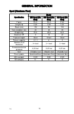
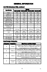
Page 21: ...e above procedure does not work reach into the boat and partly deflate the side hull tube by 50 and repeat the above procedure Quicksilver Inflatable Specifications Tendy Light Tender Specification Model 200 Tendy Slatted 200 Tendy Air Floor 240 Tendy Slatted 240 Tendy Air Floor Fabric PVC PVC PVC PVC Length m 2 00 2 00 2 40 2 40 Beam cm 134 134 134 134 Tube diameter cm 35 35 40 40 Weight kg 16 8 ...

Page 22: ...2 0 Maximum HP 5 15 20 Transom height Short Short Short Person capacity 3 1 4 5 Number of air chambers 3 keel floor 3 keel floor 3 keel floor Recommended air pressure 0 25 bar 0 25 bar 0 25 bar Keel Inflatable keel Inflatable keel Inflatable keel Floor system Inflatable air floor Inflatable air floor Inflatable air floor ISO standard 6185 6185 6185 CE category D C C GENERAL INFORMATION 14 eng ...

Page 23: ...40 40 Weight kg 35 0 49 0 54 0 Maximum HP 8 15 20 Transom height Short Short Short Person capacity 3 1 4 5 Number of air chambers 3 keel 3 keel 3 keel Recommended air pressure 0 25 bar 0 25 bar 0 25 bar Keel Inflatable keel Inflatable keel Inflatable keel Floor system Aluminum floor Aluminum floor Aluminum floor ISO standard 6185 6185 6185 CE category D C C GENERAL INFORMATION eng 15 ...

Page 24: ...cm 40 45 45 Weight kg 79 0 89 0 110 0 Maximum HP 25 40 60 Transom height Short Short Long Person capacity 6 8 10 Number of air chambers 3 keel 3 keel 5 keel Recommended air pressure 0 25 bar 0 25 bar 0 25 bar Keel Inflatable keel Inflatable keel Inflatable keel Floor system Aluminum floor Aluminum floor Aluminum floor ISO standard 6185 6185 6185 CE category C C C GENERAL INFORMATION 16 eng ...

Page 25: ...ameter cm 40 40 Weight kg 38 0 41 0 Maximum HP 10 15 Transom height Short Short Person capacity 3 4 Number of air chambers 3 3 Recommended air pressure 0 25 bar 0 25 bar Keel Keel protection Keel protection Floor system V floor ultra light V floor ultra light ISO standard 6185 6185 CE category D D GENERAL INFORMATION eng 17 ...

Page 26: ...5 CE category C C C C Boat Design Categories Categories Navigation Wind Force and Wave Height A Ocean Designed for extended voyages where conditions may exceed wind force 8 Beaufort scale and wave heights of 4 m 13 ft and higher B Offshore Designed for offshore voyages where conditions may experience wind force 8 Beaufort scale and wave heights up to 4 m 13 ft C Inshore Designed for voyages in coa...

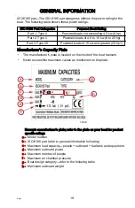
Page 27: ...late The manufacturer s plate is located on the inside of the boat transom Never exceed the maximum values as mentioned on the plate Example manufacturer s plate refer to the plate on your boat for product specific ratings a Model number b ISO 6185 part refer to general information following c Maximum load capacity people outboard fuel tank and equipment d Maximum outboard power e Maximum number o...

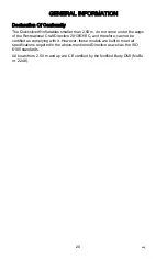
Page 28: ...raft Directive 2013 53 EC and therefore cannot be certified as complying with it However these models are built to meet all specifications required in the above mentioned Directive as well as the ISO 6185 standards All boats from 2 50 m and up are CE certified by the Notified Body DMI NoBo nr 2248 GENERAL INFORMATION 20 eng ...

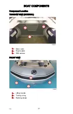
Page 29: ...Component Location TRANSOM VIEW EXTERNAL 1 Drain valve 2 Engine plate 3 WIN number FRONT VIEW 1 Lifting handle 2 Towing d ring 3 Rubbing strake 1 2 3 66426 1 2 2 3 66427 BOAT COMPONENTS eng 21 ...

Page 30: ...M VIEW COCKPIT 1 Drain valve 2 Engine plate 3 Manufacturer s plate 4 Drain valve SIDE VIEW 1 Aluminum oars 2 Air chamber valve 3 Fuel tank straps 4 Lifeline 66429 1 2 3 4 1 2 3 4 66431 BOAT COMPONENTS 22 eng ...

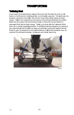
Page 31: ... they will prohibit boat movement Make sure to protect the air chamber tubes so they will not get chafed or damaged from the tie down straps Trailer your boat with the outboard tilted down in a vertical operating position If additional ground clearance is required the outboard should be tilted up using an accessory outboard support device Refer to your local dealer for recommendations Additional c...

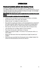
Page 32: ...stick together Deflate the keel and deflate the boat for about 2 3 Place the front section bow board 1 of the floorboard as far in the front of the boat as possible Make sure the hole in the bottom is straight above the valve of the keel section Place the side with the sticker face down Place part two into the boat Put the two parts of the floorboard in line Take part three and eventually part fou...

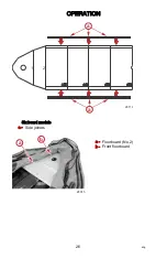
Page 33: ... Floorboards are numbered from the bow Five board models a Side joiners 1 2 a a 24097 OPERATION eng 25 ...

Page 34: ...Six board models a Side joiners a Floorboard No 2 b Front floorboard 1 2 a a 24114 24015 b a OPERATION 26 eng ...

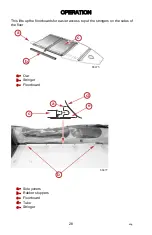
Page 35: ...ush down Installation of the Aluminum Stringer After installation of the floorboards put the stringers in the sides of the floor To install the stringers easily put an oar paddle under the bottom of the boat a b 24115 a 24118 OPERATION eng 27 ...

Page 36: ...e floorboards for easier access to put the stringers on the sides of the floor a Oar b Stringer c Floorboard a Side joiners b Rubber stoppers c Floorboard d Tube e Stringer a 66475 c b a b c d e 66477 OPERATION 28 eng ...

Page 37: ...at the back of the floor through the track 1 Put the flaps A at the after side of the floor in the transom track B b 66478 a a b 2 Install the thrust board C at the forward most point of the port and starboard tubes The thrust board must be placed under the air floor and on top of the keel D on the reinforced spot that you find on the inside in front of the tubes b a d 66479 c 3 Place the deflated...

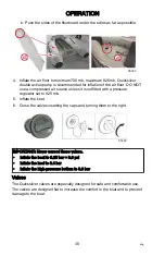
Page 38: ...ith a pressure regulator set to 825 mb 5 Inflate the keel 6 Close the valves inserting the caps and turning them to the right 66482 IMPORTANT Never exceed these values Inflate the boat to 0 25 bar 3 6 psi Inflate the keel to 0 4 bar Inflate the high pressure bottom to 0 8 bar Valves The Quicksilver valves are especially designed for safe and comfortable use The valves are designed flat to increase...

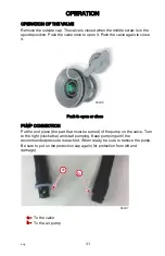
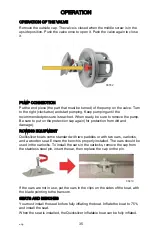
Page 39: ...ush to open or close PUMP CONNECTION Put the end piece the part that must be turned of the pump on the valve Turn to the right clockwise and start pumping Keep pumping until the recommended pressure is reached When ready be sure to remove the pump Be sure to put on the protection cap again for protection from dirt and damage a To the valve b To the air pump a b 66487 OPERATION eng 31 ...

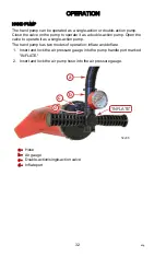
Page 40: ...alve to operate it as a single action pump The hand pump has two modes of operation inflate and deflate 1 Insert and lock the air pressure gauge into the pump handle port marked INFLATE 2 Insert and lock the air pump hose into the air pressure gauge a Hose b Air gauge c Double action single action valve d Inflate port a b c d INFLATE 52296 OPERATION 32 eng ...

Page 41: ...t is fully inflated Insert the flanges in the PVC slide glued on each top of the tube 66539 a Install the floorboards slates aluminum air deck into the boat Refer to Floorboard Installation section b Unscrew the valve caps by turning a quarter of a turn counterclockwise c Ensure that the valve stems are in the closed position d Insert the air hose adapter into the air valve 52297 a b OPERATION eng...

Page 42: ...ll cause the air pressure to fluctuate depending on water temperature and weather conditions A boat that is correctly inflated may experience a drop in air pressure and require additional air when temperatures decrease or it may become over inflated when in direct sunlight or as the temperatures increase This will require the air chamber to be deflated until the recommended air pressure is reached...

Page 43: ...m dirt and damage ROWING EQUIPMENT Quicksilver boats come standard with two paddles or with two oars oarlocks and a wooden seat Ensure the bench is properly installed The oars should be used in the oarlocks To install the oars in the oarlocks remove the cap from the stainless steel pin insert the oar then replace the cap on the pin 66419 If the oars are not in use put the oars in the clips on the ...

Page 44: ... to the open position and the water will automatically run out The inner diaphragm will prevent water from returning After the water has been drained slide the drain to the closed position 66423 Plug Drain Valve Operation When underway remove the plug from the drain and the water will automatically run out The inner diaphragm will prevent water from returning After the water has been drained repla...

Page 45: ...ion and deflation is essential for a long life of your boat To inflate the boat roll out the boat on the floor Remove any sharp objects from flat surface where the boat will be assembled If the boat is unpacked check if all parts are present Check if the valves are closed by removing the safety cap from the valve When the central button is positioned upwards the valve is closed Get your delivered ...

Page 46: ...s in right order until the inflating deflating valve starts leaking again If inflation is done in the right order the boat has the correct pressure and there is no distortion of fabric near the bulkheads IMPORTANT Never exceed these values Inflate the boat to 0 25 bar 3 6 psi Inflate the keel to 0 4 bar Inflate the high pressure bottom to 0 8 bar NOTICE Avoid structural damage due to overinflation...

Page 47: ...flation pressure of the air chambers Remove any obstruction from the drain valve Check the outboard for tightness on the transom Know the fuel capacity and cruising range Check that the lanyard stop switch for the outboard works correctly Be sure the boat is not overloaded Do not exceed the maximum number of passengers or load capacity Look at the boat capacity plate Be sure there is an approved p...

Page 48: ...d load capacity of the boat Position and distribute the load evenly in the boat to help counterbalance the weight of the outboard 14775 PASSENGER SEATING Sitting on the buoyancy tube while the boat is underway puts you at risk of being ejected during sharp turns or when in rough water You may be struck by the engine or propeller if you fall from a moving boat The operator and passengers should sit...

Page 49: ...ty Remove the outboard fuel tank and equipment Attach a line between the towing rings to form a bridle Attach a towing line to this bridle and tow the boat at slow speed 17354 Air Chamber Deflates Accidentally If one of the air chambers should accidentally deflate while you are operating the boat shift the weight to the opposite side of the deflated air chamber and slowly head for shore OPERATION ...

Page 50: ...nate water from condensation in the inner hull The deck drain plug should be removed only when the boat is under power in forward motion or when the boat is stored out of the water on davits or boat storage racks exposed to rain and water SUNLIGHT Avoid the boat to be exposed to sunshine for a longer period The changing air pressure inside the tubes might cause damage to your boat Extreme sunshine...

Page 51: ...ow altitude and transported to a high altitude for example for use in a mountain lake the air pressure must be reduced at the higher altitude to prevent an overinflation Cleaning Procedure NOTE Gasoline spillage must be cleaned immediately to prevent damage to fabric Remove the floorboards to clean the gasoline spillage from the floor fabric 1 Deflate the boat and remove the floorboards 2 Reinflat...

Page 52: ... cap 1 Remove the valve cap turn it a quarter turn counterclockwise 2 Push the valve stem in and deflate the front air chamber a quarter of the way 3 Push the valve stems in on the side air chambers and release the air pressure a quarter of the way 4 Repeat this procedure to evenly deflate all of the air chambers 5 Push in the valve stem and turn the stem a quarter turn clockwise to lock the valve...

Page 53: ...ing Instructions 1 Deflate the boat following the deflating instructions Keep the air valves open 2 Remove the seat if equipped paddles floorboards and any equipment 3 Fold the deflated sides inward until the sides meet in the middle 4 Fold the boat transom inward and then fold in the two rear cones inward over the transom 23507 a b DEFLATE 52299 MAINTENANCE eng 45 ...

Page 54: ...d soap on and around the valves If you see air bubbles around the valves take the following steps Take the valve key from your repair kit 66541 Put the valve key into the valve turn the key clockwise and check for air bubbles again If the valve still leaks take back of valve in your hand turn the valve stem with the key to the left counterclockwise and take out the valve stem MAINTENANCE 46 eng ...

Page 55: ...e defective valve to your selling dealer You will receive a new valve Install and lubricate the valve stem with silicone or soapy water solution to ease installation In case of persistent air leakage contact your dealer and check warranty conditions MAINTENANCE eng 47 ...

Page 56: ...er Service Center closest to you for assistance purchasing the correct type of glue adhesive for your product Small tears and punctures in the air chambers that are 1 cm 0 393 in or less can be repaired in an emergency Larger areas or if the patch will overlap a seam should be patched by a professional repair technician at an inflatable repair station Contact your local Mercury dealer for the near...

Page 57: ...for repairing inflatables are toxic and highly flammable As a safety precaution always work outdoors or in an area that is well ventilated and away from any open flames sparks or appliances equipped with pilot lights Breathing the vapors or exposure to the skin may be hazardous to your health Avoid breathing the vapors and contact with skin and eyes by wearing a carbon filter respirator and protec...

Page 58: ...PART CATALYST ADHESIVE Mix a batch of adhesive according to the directions provided with the adhesive Do not allow the adhesive to contact your skin When the adhesive is fully mixed it must sit for a short time to activate the catalyst Failure to allow sufficient time for the catalyst to alter the adhesive compounds will cause poor fabric adhesion Apply three thin layers of adhesive with a short b...

Page 59: ...re the boat in water for extended periods of time Clean the boat fabric and air deck floor following the Cleaning Procedure in the Maintenance section Dry the boat thoroughly after washing The boat can be stored inflated or deflated Store the boat in a cool dry area that is protected from excess exposure from the sun Cover the boat to block direct sunlight exposure when the boat is stored outside ...

Page 60: ...it to your authorized dealer Only authorized dealers specialize in Mercury products and have factory trained mechanics special tools and equipment and genuine Quicksilver parts and accessories to properly service your engine NOTE Quicksilver parts and accessories are engineered and built by Mercury Marine specifically for your power package SERVICE AWAY FROM HOME If you are away from your local de...

Page 61: ...ssories from the factory Mercury Marine does not sell to unauthorized dealers or retail customers When inquiring about parts and accessories the dealer requires the engine model and serial numbers to order the correct parts RESOLVING A PROBLEM Satisfaction with your Mercury product is important to your dealer and to us If you ever have a problem question or concern about your power package contact...

Page 62: ...175 Australia Fax 61 3 9706 7228 Europe Middle East Africa Telephone 32 87 32 32 11 Brunswick Marine Europe Parc Industriel de Petit Rechain B 4800 Verviers Belgium Fax 32 87 31 19 65 Mexico Central America South America Caribbean Telephone 1 954 744 3500 Mercury Marine 11650 Interchange Circle North Miramar FL 33025 U S A Fax 1 954 744 3535 Japan Telephone 072 233 8888 Kisaka Co Ltd 4 130 Kannabe...

Page 63: ...OUTSIDE THE UNITED STATES AND CANADA Contact your nearest Mercury Marine authorized service center to order additional literature that is available for your particular power package Submit the following order form with payment to Mercury Marine Attn Publications Department W6250 Pioneer Road P O Box 1939 Fond du Lac WI 54936 1939 Ship To Copy this form and print or type This is your shipping label...

Reviews: