background image

BOAT COMPONENTS

20

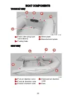
TRANSOM VIEW

a

b

c

b

d

18026

a -

Drain valve (plug type

valve shown)

b -

Towing holes

c -

Motor plate

d -

Manufacturer's plate

SIDE VIEW

a

b

c

d

18083

e

a -

Port air chamber valve

b -

Front air chamber valve

c -

Keel air chamber valve

d -

Starboard air chamber

valve

e -

Oars

Summary of Contents for Sport 240

Page 1: ...ommended for anyone who is not familiar with the rules and regulations on operating a boat Please read and understand this manual carefully before operating your inflatable boat Warranty Message The product you have purchased comes with a limited warranty from Mercury Marine The terms of the warranty are set forth in the Warranty Information Section of this manual The warranty statement contains a...

Page 2: ...ne HIN Engine Serial Number Engine Model Number Mercury Marine Fond du Lac Wisconsin U S A Litho in U S A 2006 Mercury Marine Mercury Mercury Marine MerCruiser Mercury MerCruiser Mercury Racing Mercury Precision Parts Mercury Propellers Mariner Quicksilver 1 On The Water Alpha Bravo Pro Max OptiMax Sport Jet K Planes MerCathode RideGuide SmartCraft Zero Effort M with Waves logo Mercury with Waves ...

Page 3: ...fore Operating Your Boat 6 Lanyard Stop Switch 7 Protecting People In The Water 9 Wave And Wake Jumping 10 Impact With Underwater Hazards 11 Exhaust Emissions 12 Safe Boating Suggestions 14 Specifications 15 Manufacturer s Plate 17 BOAT COMPONENTS Components Location 19 TRANSPORTING Trailering Boat 21 OPERATION Floorboard Installation 22 Inflating 26 Outboard Power 28 Pre Operating Check List 28 D...

Page 4: ...1 Beaching 31 MAINTENANCE Cleaning Procedure 32 Deflating 32 Folding Instructions 33 REPAIRS Air Chamber Repair PVC Fabric 35 STORAGE Storage Preparation 37 OWNERS SERVICE ASSISTANCE Service Assistance 38 Parts And Accessories Inquiries 38 Service Away From Home 38 ...

Page 5: ...nd du Lac WI 54936 1939 920 929 5054 Fax 920 929 5893 Upon processing the transfer of warranty Mercury Marine will send registration verification to the new owner of the product by mail There is no charge for this service For products purchased outside the United States and Canada contact the distributor in your country or the Marine Power Service Center closest to you Warranty Registration United...

Page 6: ...it to Mercury Marine via MercNET E mail or mail Upon receipt of this warranty registration Mercury Marine will record the registration 3 Upon processing the warranty registration Mercury Marine will send registration verification by mail to the purchaser of the product If this registration verification is not received within 30 days please contact your selling dealer immediately Warranty coverage ...

Page 7: ... MUST BE MET IN ORDER TO OBTAIN WARRANTY COVERAGE Warranty coverage is available only to retail customers that purchase from a Dealer authorized by Mercury Marine to distribute the product in the country in which the sale occurred Warranty coverage becomes available upon proper registration of the product by the authorized dealer Routine maintenance outlined in the Operation and Maintenance Manual...

Page 8: ...rder to obtain coverage WHAT IS NOT COVERED This Limited Warranty does not cover routine maintenance items adjustments normal wear and tear puncture discoloration oxidation abrasion or damage caused by abuse abnormal use neglect accident improper service use of an accessory or part not manufactured or sold by Mercury Marine or alteration or removal of parts Use of the product for racing or other c...

Page 9: ...S ARE LIMITED IN DURATION TO THE LIFE OF THE EXPRESS WARRANTY INCIDENTAL AND CONSEQUENTIAL DAMAGES ARE EXCLUDED FROM COVERAGE UNDER THIS WARRANTY SOME STATES COUNTRIES DO NOT ALLOW FOR THE DISCLAIMERS LIMITATIONS AND EXCLUSIONS IDENTIFIED ABOVE AS A RESULT THEY MAY NOT APPLY TO YOU THIS WARRANTY GIVES YOU SPECIFIC LEGAL RIGHTS AND YOU MAY ALSO HAVE OTHER LEGAL RIGHTS WHICH VARY FROM STATE TO STATE...

Page 10: ...perate your boat properly If you have any questions contact your dealer Safety and operating information that is practiced along with using good common sense can help prevent personal injury and product damage This manual uses the following safety alerts to draw your attention to special safety instructions that should be followed WARNING WARNING indicates a potentially hazardous situation that if...

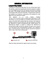
Page 11: ... 152 cm 4 and 5 feet in length when stretched out with an element on one end made to be inserted into the switch and a snap on the other end for attaching to the operator The lanyard is coiled to make its at rest condition as short as possible to minimize the likelihood of lanyard entanglement with nearby objects Its stretched out length is made to minimize the likelihood of accidental activation ...

Page 12: ...hallow or obstacle infested waters releasing your grip on a steering wheel or tiller handle that is pulling in one direction drinking alcohol or consuming drugs or daring high speed boat maneuvers While activation of the lanyard stop switch will stop the engine immediately a boat will continue to coast for some distance depending upon the velocity and degree of any turn at shut down However the bo...

Page 13: ...nt of the boat who could be ejected over the bow and possibly struck by the gearcase or propeller Loss of power and directional control in heavy seas strong current or high winds Loss of control when docking Protecting People In The Water WHILE YOU ARE CRUISING It is very difficult for a person standing or floating in the water to take quick action to avoid a boat heading in his her direction even...

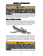
Page 14: ...ing However when this activity is done with sufficient speed to force the boat hull partially or completely out of the water certain hazards arise particularly when the boat re enters the water 14463 The primary concern is the boat changing direction while in the midst of the jump In such case the landing may cause the boat to veer violently in a new direction Such a sharp change in direction can ...

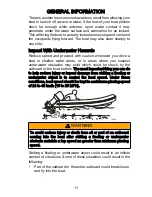
Page 15: ...ter obstacles may exist which could be struck by the outboard or the boat bottom The most important thing you can do to help reduce injury or impact damage from striking a floating or underwater object is to control the boat speed Under these conditions boat speed should be kept to a minimum planing speed of 24 to 40 km h 15 to 25 MPH 14462 WARNING To avoid serious injury or death from all or part...

Page 16: ...lso be checked for any hull fractures transom fractures or water leaks Operating a damaged outboard could cause additional damage to other parts of the outboard or could affect control of the boat If continued running is necessary do so at greatly reduced speeds WARNING Avoid serious injury or death from loss of boat control Continued boating with major impact damage can result in sudden component...

Page 17: ...tain running and or wind conditions permanently enclosed or canvas enclosed cabins or cockpits with insufficient ventilation may draw in carbon monoxide Install one or more carbon monoxide detectors in your boat Although the occurrence is rare on a very calm day swimmers and passengers in an enclosed area of a stationary boat that contains or is near a running engine may be exposed to a hazardous ...

Page 18: ...ks and required maintenance Follow a regular schedule and ensure that all repairs are properly made Know and obey all nautical rules and laws of the waterways Boat operators should complete a boating safety course Courses are offered in the U S A by 1 The U S Coast Guard Auxiliary 2 The Power Squadron 3 The Red Cross and 4 your state boating law enforcement agency Inquiries may be made to the Boat...

Page 19: ...ter skier in case the skier falls As an example your boat traveling at 40 km h 25 MPH will overtake a fallen skier 61 m 200 ft in front of you in 5 seconds Watch fallen skiers When using your boat for water skiing or similar activities always keep a fallen or down skier on the operator s side of the boat while returning to assist the skier The operator should always have the down skier in sight an...

Page 20: ...173 5 cm 5 ft 8 in 204 cm 6 ft 8 in 229 cm 7 ft 6 in Outer width 152 cm 5 ft 0 in 152 cm 5 ft 0 in 152 cm 5 ft 0 in 152 cm 5 ft 0 in Inner width 72 cm 2 ft 4 in 72 cm 2 ft 4 in 72 cm 2 ft 4 in 72 cm 2 ft 4 in Tube diameter 40 cm 16 in 40 cm 16 in 40 cm 16 in 40 cm 16 in Recommended tube air pressure 0 25 bar 3 6 psi 0 25 bar 3 6 psi 0 25 bar 3 6 psi 0 25 bar 3 6 psi Recommended keel air pressure 0...

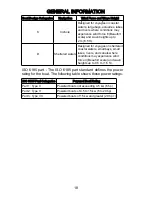
Page 21: ...chambers g Maximum outboard power h Maximum number of people i ISO 6185 part see following table Boat design category The following table shows the navigation use that the boat was designed and constructed for Boat Design Categories Navigation Wind Force and Wave Height A Ocean Designed for extended voyages where conditions may exceed wind force 8 Beaufort scale and wave heights of 4 m 13 ft and a...

Page 22: ...es on sheltered coastal waters small bays small lakes rivers and canals where conditions may experience wind force 4 Beaufort scale and wave heights up to 0 5 m 1 5 ft ISO 6185 part The ISO 6185 part standard defines the power rating for the boat The following table shows these power ratings ISO 6185 Part Categories Powered Boat Rating Part 1 Type ll Powered boats not exceeding 4 5 kw 6 hp Part 2 ...

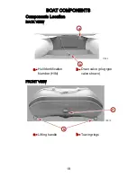
Page 23: ...BOAT COMPONENTS 19 Components Location BACK VIEW a b 17345 a Hull Identification Number HIN b Drain valve plug type valve shown FRONT VIEW a b 18012 a Lifting handle b Towing rings ...

Page 24: ...c b d 18026 a Drain valve plug type valve shown b Towing holes c Motor plate d Manufacturer s plate SIDE VIEW a b c d 18083 e a Port air chamber valve b Front air chamber valve c Keel air chamber valve d Starboard air chamber valve e Oars ...

Page 25: ...raps down securely so they will prohibit boat movement Make sure to protect the air chamber tubes so they will not get chafed or damaged from the tie down straps Trailer your boat with the outboard tilted down in a vertical operating position If additional ground clearance is required the outboard should be tilted up using an accessory outboard support device Refer to your local dealer for recomme...

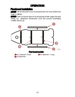
Page 26: ... into the boat before the boat is inflated NOTE Each H channel should be installed with the larger flat side facing up Assemble floorboards with the printed identifying number facing up 1 2 3 4 a b b c c 18129 Four board models a H channel Short b Side joiner c H channel Long ...

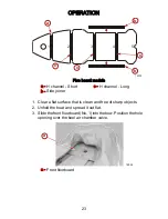
Page 27: ...Short b Side joiner c H channel Long 1 Clear a flat surface that is clean and free of sharp objects 2 Unfold the boat and spread it out flat 3 Slide the front floorboard No 1 into the bow Position the hole opening over the keel air chamber valve a 18092 a Front floorboard ...

Page 28: ...OPERATION 24 4 Slide the rear floorboard No 4 or 5 under the transom retainer a b 18094 a Rear floorboard b Transom retainer ...

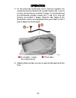
Page 29: ...shape On models having five floorboards position boards No 3 and 4 so they are forming an inverted V shape Align the side edges of the floorboards so they are straight and then push down on the V joint to flatten the floorboards b a 10139 a H channels Larger flat side facing up b Push down 6 Slightly inflate the keel in order to raise the floorboards off the floor ...

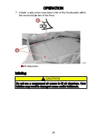
Page 30: ...r onto each side of the floorboards within the recessed portion of the floor a a 18141 a Side joiners Inflating CAUTION Do not use a compressed air source to fill air chambers Over inflation may result in damaged seams and or bulkheads ...

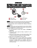
Page 31: ... NOTE Install the removable seat before the boat is fully inflated Hook the flanges that are located on the bottom of the seat into the nylon straps on the side air chambers a Fit the floorboards into the boat Refer to Floorboard Assembly b Unscrew the valve caps by turning a quarter of a turn counterclockwise c Make sure the valve stems are in the closed position Push in on the valve stem and rot...

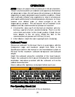
Page 32: ...0 25 bar 3 6 psi 3 After inflation install the valve caps tight turn clockwise Outboard Power Choose an outboard for the boat that is in accordance with the horsepower range and maximum weight limit Refer to the Specification table in this manual or the manufacturer s plate on the boat for the maximum outboard horsepower and outboard weight Install the outboard along the centerline of the boat tra...

Page 33: ...ure the operator knows safe navigation boating and operating procedures Be sure there is a ring type life buoy or buoyant cushion designed to be thrown to a person in the water Arrange the passengers and load in the boat so the weight is distributed evenly and everyone is seated in a proper seat or on the floor Instruct at least one passenger in the basics of boat handling and the starting and ope...

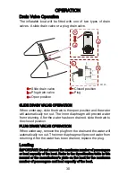
Page 34: ...aphragm will prevent water from returning After the water has been drained slide the drain to the closed position PLUG DRAIN VALVE OPERATION When underway remove the plug from the drain and the water will automatically run out The inner diaphragm will prevent water from returning After the water has been drained replace the plug Loading IMPORTANT Do not exceed the maximum number of passengers or l...

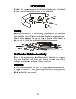
Page 35: ...between the towing rings to form a bridle Attach a towing line to this bridle and tow the boat at slow speed 17354 Air Chamber Deflates Accidently If one of the air chambers should accidently deflate while you are operating the boat shift the weight to the opposite side of the deflated air chamber and slowly head for shore Beaching It is recommended that the boat not be powered onto the beach drag...

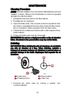
Page 36: ...ean both the exterior and interior with a mild soap and fresh water solution 5 Rinse with fresh water and dry thoroughly IMPORTANT Do not use a vinyl preservative on the air chamber fabric Chemicals in the preservatives may dry out the fabric Deflating IMPORTANT When deflating the side air chambers do not deflate one side air chamber at a time When deflating maintain a balanced air pressure betwee...

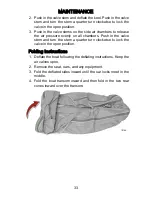
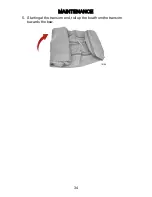
Page 37: ...ure evenly on all chambers Push in the valve stem and turn the stem a quarter turn clockwise to lock the valve in the open position Folding Instructions 1 Deflate the boat following the deflating instructions Keep the air valves open 2 Remove the seat oars and any equipment 3 Fold the deflated sides inward until the oar locks meet in the middle 4 Fold the boat transom inward and then fold in the t...

Page 38: ...MAINTENANCE 34 5 Starting at the transom end roll up the boat from the transom towards the bow 18168 ...

Page 39: ... Mercury Marine Small tears and punctures in the air chambers which are 1 cm 0 393 in or less can be repaired in an emergency Larger areas or if the patch will overlap a seam should be patched by a professional repair technician at an inflatable repair station Contact your local Mercury dealer for the nearest inflatable repair station For the best results when gluing the relative humidity should b...

Page 40: ...ristle brush in a circular pattern on both the backside of the patch and the patch area on the boat Allow each layer to dry for 5 10 minutes before applying the next layer After applying the third layer wait 5 10 minutes and then apply the patch to the prepared area and press down firmly Using a smooth object a back of a tablespoon works well force out any air bubbles that may have been trapped un...

Page 41: ...marine growth or polluted waters do not store the boat in water for extended periods of time After washing allow the boat to dry thoroughly before placing into storage The boat can be stored inflated or deflated Store the boat in a cool dry area that is protected from excess exposure from the sun Cover the boat to block direct sunlight exposure if the boat is to be stored outside for an extended p...

Page 42: ...ve all problems The following information will be needed by the service office Your name and address Daytime telephone number Model and serial number of your outboard Model and serial number of your inflatable boat The name and address of your dealership Nature of problem Parts And Accessories Inquiries All inquiries concerning genuine replacement parts and accessories should be directed to your l...

Reviews: