11/11/2006
8 Rev 2.0
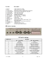
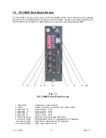
Function
Description
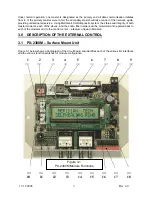
1. Button 2
- button for submenu scrolling
2. Button 1
- button for main menu scrolling
3. Connector RJ45
- RS-232/485 interface for SpectraSmart PC diagnostic
4. Connector USB “B” - USB interface for SpectraSmart PC diagnostic
5. Connector 2PIN - alarm relay contact closure
6. Connector DB-25
- input / output data stream
7. Jumpers 1 - 12
- interface mode selected
8. 2-Pin Connector - redundant power input (PWR B)
9. 2-Pin Connector - main power input (PWR A)
10 Potentiometer - LCD contrast adjust
11 Speaker - audible alarm
12 Rotary switches - modem address setting
13 Optic port 2 - transmit ring B – Tx B and receive ring A – Rx A
14. LCD - liquid crystal display
15. Optic port 1 - transmit ring A - Tx A and receive ring B - Rx B
16. Jumpers 13 - 24 - antistream value
17. DIP switch - configuration mode selected
18. LEDs - electrical & optical status indicators
DIP
SWITCH FUNCTION
DIP switch settings
SWITCH NO.
SETTING
ON ( up position)
OFF (down position)
1 Master
Slave
2 Primary
Master
Secondary Master
3 Ring
Configuration String / Bus Configuration
4
RS 232 Port Enabled
RS 232 Port Disabled
5
RS 422 Port Enabled
RS 422 Port Disabled
6
RS 485 (2 wire) Port Enabled
RS 485 (2 Wire) Port Disabled
7
RS 485 (4 wire) Port Enabled
RS 485 (4 Wire) Port Disabled
8
TTL Port Enabled
TTL Port Disabled
9
Remote Loop back Enabled
Remote Loop back Disabled
10
Local Loop back Enabled
Local Loop back Disabled
11 Buzzer
Enabled
Buzzer Disabled
12
Anti Streaming Enabled
Anti Streaming Disabled
Summary of Contents for 2300M Series
Page 6: ...PX 2300 SELF HEALING RING MULTIDROP FIBER OPTIC MODEM User s Manual...
Page 28: ...11 11 2006 23 Rev 2 0...
Page 44: ......

