11/11/2006
9 Rev 2.0
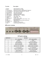
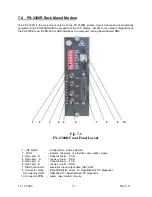
The 12-position DIP switch is located on the right side of the front panel.
The data format is selected by setting DIP switches 4 through 8. The available data formats are RS-232,
RS-422, RS-485 (2-wire or 4-wire) and TTL.
The local audible alarm can be enabled/disabled by setting switch 11.
Anti-Streaming is enabled & disabled via switch 12.
The modem status (Master primary/secondary or Slave) and network configurations (string/ring) are set
by switches 1, 2 & 3.
Please note that the position of these individual switches is detected when power is applied to the
specific modem. If these positions are changed while the modem is operational, it will be necessary to
reset the modem either by briefly removing power to the modem or (for a master modem) by using the
pushbuttons to ‘RESTART’ the modems. This reset function properly configures the modem to any new
settings that may have been changed.
3.2 Rotary switches
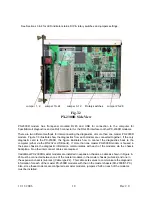
The three rotary switches located on the front of the modem are used by the internal diagnostics to
properly identify and communicate with each modem. Master modems can be set between 0 and 99
while each of the slave modems can be set from 1 to 99 (there is no #0 for slaves). Note that it is
important to set the slaves using consecutive numbers starting from 1 (closest to the Master).
The switches are factory set to ‘000’. This position is identified by the arrows on the switches in the 9
O’clock position. A small slotted screwdriver is used to set these switches.
3.3 LEDs status
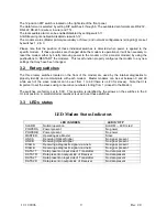
LED Modem Status Indicators
LED IS GREEN
LED IS ‘OFF’
ALARM
Normal operation
ALARM -- LED is red
POWER A
Power present
No power
POWER B
Power present
No power
MASTER
Operating as a Master
Slave
LINK A
Receiving Optical Signal
No signal present
LINK B
Receiving Optical Signal
No signal present
DIAG A
Receiving a diagnostic signal via Line A
No signal present
DIAG B
Receiving a diagnostic signal via Line B
No signal present
DATA 1T
Data present on input side of Transmitter
No data present
DATA 1R
Data present on output side of Receiver
No data present
DATA 2T
Data present on input side of Transmitter
No data present
DATA 2R
Data present on output side of Receiver
No data present
Summary of Contents for 2300M Series
Page 6: ...PX 2300 SELF HEALING RING MULTIDROP FIBER OPTIC MODEM User s Manual...
Page 28: ...11 11 2006 23 Rev 2 0...
Page 44: ......

