11/11/2006
18 Rev 2.0
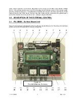
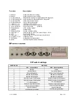
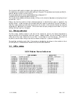
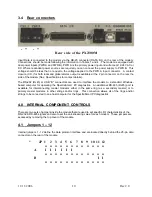
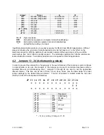
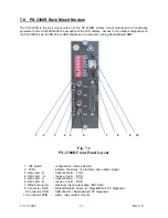
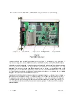
See Sections 3 & 4 for LED indicator status, DIP & rotary switches and jumpers settings.
Jumper 1, 2
Jumper 13–24 Jumper 3–12 Rotary switches
Jumper 25–28
Fig.7-2
PX-2300R Side View
PX-2300R modem has front-panel mounted RJ45 and USB for connection to the computer for
SpectraSmart diagnostics and an RJ45 connector for the RS-485 interface to other PX-2300R modems.
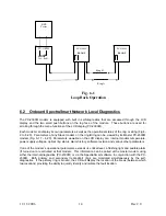
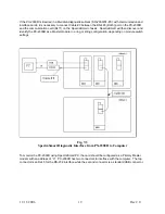
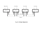
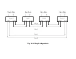
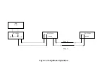
There are two different methods for interconnecting the diagnostics of more than one master PX-2300R
modem. Figure 7-3 illustrates how the diagnostics from each modem are connected together. If the only
diagnostic card is the PX-2300R, this figure illustrates how to connect the diagnostics back to the
computer (either via the RS-232 or USB ports). If more than one master PX-2300R modem is housed in
the same chassis, the diagnostic information communicates with each of the modems via the chassis
backplane. No other interconnect cables are required.
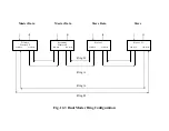
If additional PX-2300R master modems are installed in expansion chassis, a cable as shown in Figure 6-
23 must be connected between one of the master modems in the master chassis (subrack) and one in
the expansion chassis (subrack) (Cable type #2). This cable acts serves to communicate the diagnostic
information for each of the master PX-2300R modems with that in the master chassis (SR-2000/S1-PC).
Also, since these modems are configured as master modems, jumpers 25-28 on each of the modems
must be installed.
Summary of Contents for 2300M Series
Page 6: ...PX 2300 SELF HEALING RING MULTIDROP FIBER OPTIC MODEM User s Manual...
Page 28: ...11 11 2006 23 Rev 2 0...
Page 44: ......

