Unpacking your speakers
Before you begin installation you should ensure that your DSP loudspeakers are the
correct voltage for your local AC supply. If they are not, do not try to install them,
and contact your dealer.
You should not make any connections to the DSP loudspeakers, or to any other
component in your system, while the AC power supply is connected and switched on.
Components
Each DSP loudspeaker system is supplied with the following components:
•
One power cord per speaker.
•
Meridian M5 lead (8m).
•
Meridian S5 lead (8m).
If any of these items is missing please contact your dealer. We suggest that you
retain the packaging carefully for maximum protection in transit.
Removing the grilles
DSP3100: The grille is held tightly in place by the side metal plates. Gently pull it
from the top edge, taking care not to scratch the high-gloss lacquer, then pull it
gently from the sides and then bottom to remove it.
DSP3100HC: The grille is held on by pegs. Gently pull from the sides and then top
and bottom to remove it.
Note:
The speakers are designed to be used with their grilles fi tted.
Master and slave
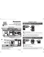
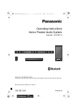
When two 3100 loudspeakers are supplied as a
pair, one speaker is preconfi gured as Left Master
and the other as Right Slave. This allows you to
set up a 2-channel system without any further
confi guration:
Cleaning the speakers
Greasy marks should be removed from the metal surfaces by light rubbing with a
slightly damp cloth and a trace of proprietary glass cleaner. Do not use any other
solvent or abrasive based cleaners.
On black speakers, small marks on the lacquer surface can usually be removed by
treating with Black Turtle Wax Color Magic. Do not use any coarse polish such as
Auto Colour restorer, and always test any polish on a non-visible area fi rst. Do not
use any polish containing a solvent; these can cause crazing of the surface.
Connections
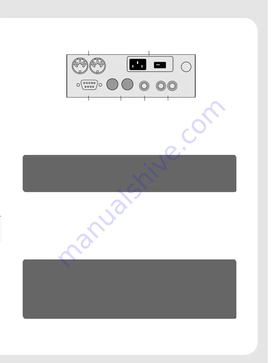
The following diagram gives details of the back panel connections:
, Ê"-
,-ÓÎÓ
"1/*1/
"1/*1/
1-
*1/
*1/
/
"1/*1/
Ê £Ê
Ó
/Ê *1/
*"7,
"
"
ÊÃ
*
Ê
Ã
}Ì>Ê
ÕÌ«ÕÌ
}Ì>Ê
«ÕÌÃ
*ÜiÀ
See overleaf for pictures of sample confi gurations.
Digital connections
The following table gives details of the digital audio connections:
Use this connection
To connect to this
DIGITAL INPUT 1,
DIGITAL INPUT 2
A digital source, such as a digital sound processor, digital
preamplifi er, CD player, or DVD player
DIGITAL OUTPUT
A second (slave) DSP loudspeaker, using an S5 lead.
The digital connections should be made with high-quality 75
Ω
screened cable.
Suitable cables are available from Meridian. We do not recommend using analogue
audio cables, which do not have adequate shielding or the correct impedance, or
cables intended for UHF applications, as these do not provide adequate shielding in
the 1–30MHz region.
Communications connections
The following table gives details of the communications connections:
Use this connection
To connect to this
COMMS INPUT
The COMMS connection on a Meridian control unit or
preamplifi er.
COMMS OUTPUT
The COMMS INPUT on a second DSP loudspeaker.
RS232
The serial port of a PC, to control the DSP loudspeaker using a
computer. For more information see the Meridian Web site,
http://www.meridian-audio.com.
The DIN Comms and BNC Comms connections are equivalent; use whichever is
appropriate for the leads supplied with your other Meridian equipment.
Left
Master
Right
Slave


