MM-34
Page 6
Revised 11-02
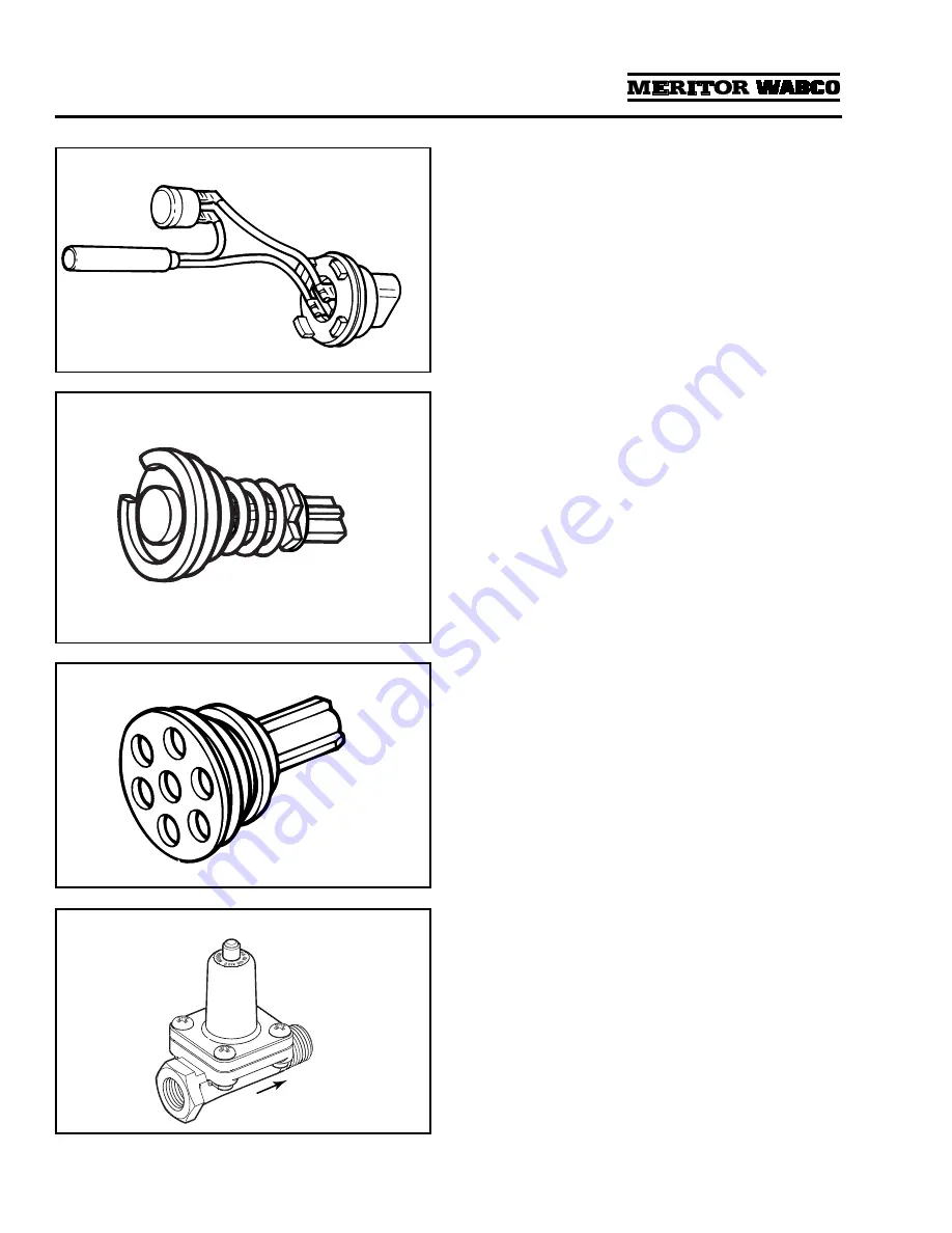
Figure 1.7
Heater:
Located in the air dryer base, the heater
prevents water that collects in the air dryer from
freezing. It consists of a cylindrical resistive-type
heating element and a small circular thermostat.
Heater is available for 12- and 24-volt air dryers.
Figure 1.7
.
1002149a
HEATER MAY BE STAINLESS
STEEL CLAD OR CERAMIC
Figure 1.8
For 1000 Series dryers with date code 0894 or earlier.
Bypass Valve:
A valve located between the inlet
and outlet ports of the dryer. It allows air to flow
into the dryer and go directly to the outlet port,
bypassing the desiccant cartridge. The 1200,
1200E Series and 1000 Series with date codes
later than 0894 do not use a bypass valve.
Figure 1.8
.
1002150a
Figure 1.9
Outlet Check Valve:
A valve located in the outlet
port (port 21) of the air dryer. It prevents air from
flowing back through the air dryer and escaping
out the purge valve during a compressor unload
cycle.
Figure 1.9
.
1002151a
Figure 1.10
Pressure-Controlled Check Valve (PCCV):
Used
with System Saver Series regeneration style air
dryers. The PCCV is usually mounted on the
secondary air tank in place of an inlet check
valve. It lets air backflow from the secondary
tank to the supply tank as long as system
pressure remains between the normal cut-in
and cut-out range of the governor. It allows
additional air volume for generation during the
air dryer purge cycle. Not used with “P” style air
dryers.
Figure 1.10
.
1002152b
AIR FLOW
DIRECTION


