Section 3
Installing Replacement Parts
MM-34
Page 18
Revised 11-02
NOTE:
For dryers with date codes of 0894 or
earlier, follow the special instructions in the
replacement kit to complete the installation.
6.
Install the new retainer and screw to hold the
element and the thermostat in place.
7.
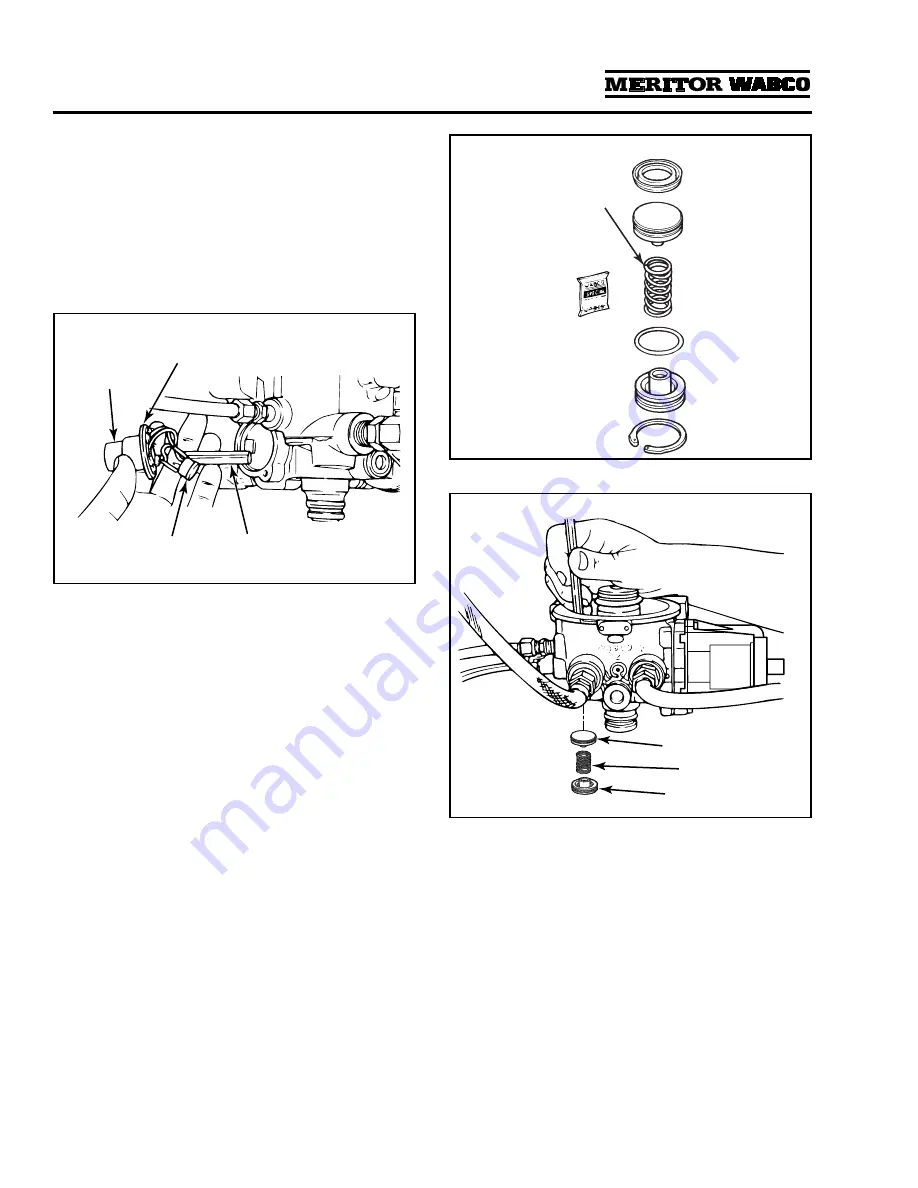
Install the new O-ring and receptacle and
fasten them in place with the screws.
Figure 3.6
.
Turbo Cut-Off Valve Assembly
NOTE:
E Series air dryers use a different turbo
cut-off valve assembly. Refer to PB-96134 for
information.
1.
Review
Figure 3.7
to make sure you have all of
the parts required to replace the turbo cut-off
valve.
Use the grease included with the replacement
kit to lubricate O-rings and seals.
2.
Remove the snap ring. The cover and spring
may fall out of the bore when the snap ring is
removed.
3.
Remove the desiccant cartridge as described
above. Use a wooden stick to push the piston,
spring and cover out of the bore.
Figure 3.8
.
4.
Clean and inspect the valve bore. If the bore is
damaged so that a tight seal cannot be
maintained, replace the air dryer.
Figure 3.8
.
5.
Install new lip seal on piston. Seal lip must
face up (toward top of piston).
6.
Install new O-ring on cover.
7.
Apply a thin layer of grease to the valve bore
and the O-rings.
8.
Install the new piston with flat side toward
dryer.
9.
Install the new spring, cover and snap ring to
hold the components in place.
10. Install plug.
11. Replace the desiccant cartridge.
Figure 3.6
1002168a
O-RING
HEATER
THERMOSTAT
RECEPTACLE
Figure 3.7
Figure 3.8
Spring not used in
U Series air dryers.
1002170a
PISTON
SPRING
COVER


