MM-34
Revised 11-02
Page 19
Regeneration Valve Assembly
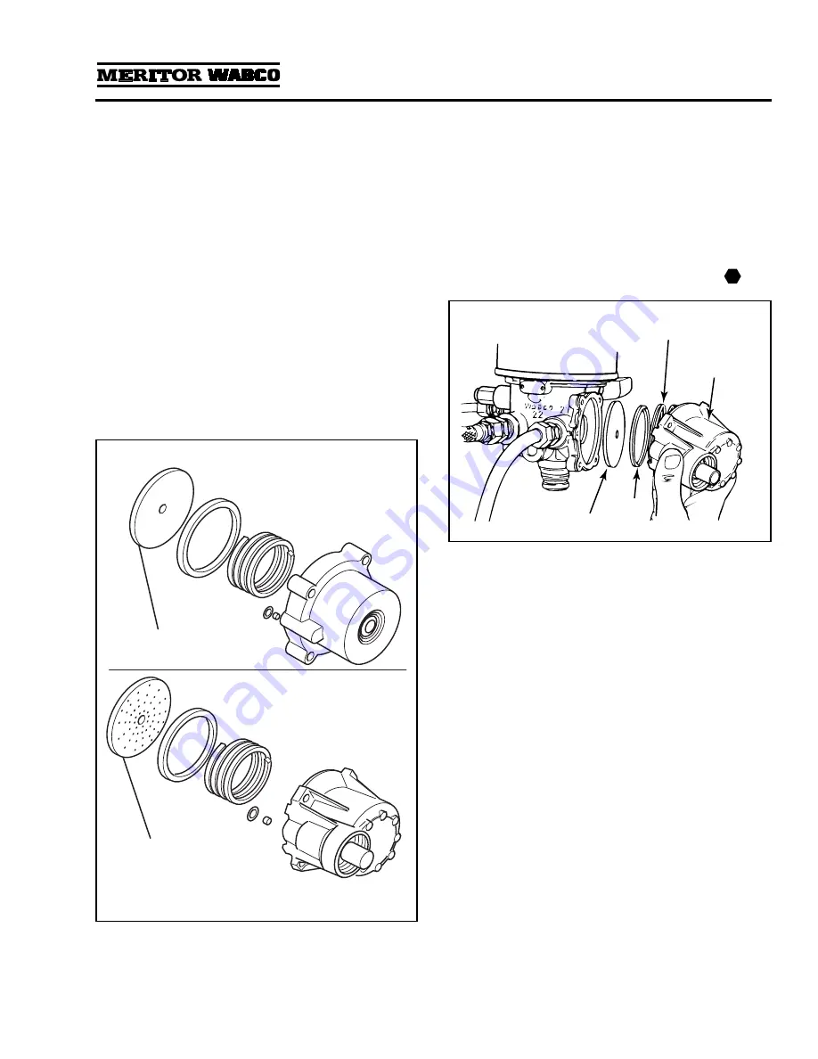
The regeneration valve assembly kit contains two
different diaphragms to service the regeneration
valve assembly for System Saver 1000, 1200 or
1800 air dryers. Use the correct diaphragm for the
style of regeneration valve housing as indicated in
the sketches below. Use of the incorrect part will
result in unsatisfactory purging of the desiccant
cartridge and may result in excess water in the air
system.
1.
Review
Figure 3.9
to make sure you have all of
the parts required to replace the regeneration
valve. Use the grease included with the
replacement kit to lubricate O-rings and seals.
2.
Remove the four mounting bolts and the valve
housing assembly. When you remove the
housing, the spring and cap will fall out.
3.
Remove the rubber diaphragm.
4.
Clean and inspect the diaphragm lip groove. If
the groove is damaged so that a tight seal
cannot be maintained, replace the air dryer.
5.
Install the new diaphragm with its lip in the
groove.
DO NOT GREASE THE DIAPHRAGM
.
6.
Install the new spring and cap with the cap lip
facing out. Install the valve housing assembly
with the new lubricated O-ring and filter over
the orifice. Install the new mounting bolts and
tighten to 53 lb-in (6 N•m).
Figure 3.10
.
Figure 3.9
INCLUDED IN KIT
The smooth diaphragm is
used with the smooth,
cylindrical Regeneration
Valve Housing.
INCLUDED IN KIT
The speckled/dotted diaphragm
is used with the finned/ribbed
die cast Housing.
Only one diaphragm is used per assembly.
DO NOT GREASE THE DIAPHRAGM.
Figure 3.10
T
1002172a
DIAPHRAGM
SPRING
VALVE
HOUSING
ASSEMBLY
CAP


