MM-34
Revised 11-02
Page 21
10. Install spring in valve head; fit valve head
assembly into bore.
NOTE:
If shims are included in the
replacement kit, they must be installed above
and below the spring. If they are not included,
they are not needed.
11. Install snap ring to hold the valve head in
place.
NOTE:
Make sure snap ring is fully seated or
assembly will leak from the purge valve.
Pressure-Controlled Check
Valve (PCCV)
WARNING
Remove all air pressure from the tank before you
remove the pressure-controlled check valve.
Pressurized air can cause serious personal injury.
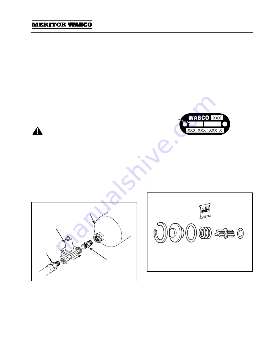
1.
Before replacing, look at the arrow on this
valve. You must install the valve so that the
arrow faces the tank on which it is installed.
Figure 3.15
.
NOTE:
New style valves have the hex nipple
pipe fitting installed.
2.
Disconnect the air line from the
pressure-controlled check valve and remove
the valve from the tank and hex nipple pipe
fitting.
3.
Install the new valve.
O
Whatever orientation (up or down) the valve
is in when it is tight is acceptable, as long as
the arrow is pointing in the right direction.
4.
Apply pipe sealant to the fittings and connect
the air line to the PC check valve.
5.
Test the installation for proper operation.
(Refer to Testing the Meritor WABCO System
Saver Series Air Dryer in this section.)
Bypass Valve
NOTE:
Used only on dryers with date codes of
0894 or earlier.
1.
Review
Figure 3.16
to make sure you have all
of the parts required to replace the bypass
valve.
Use the grease included with the replacement
kit to lubricate O-rings and seals.
2.
Remove the snap ring, cover, spring and
valve body.
3.
Clean and inspect the valve bore. If the bore
is damaged so that a tight seal cannot be
maintained, then replace the air dryer.
Figure 3.15
1002177b
PRESSURE-CONTROLLED
CHECK VALVE
TANK
HEX NIPPLE
PIPE FITTING
Arrow on
bottom of
valve must
face tank.
AIR LINE
Figure 3.16
0894
DATE
CODE
1002179a
SNAP
RING
O-RING
VALVE
BODY
SPRING
O-RING
COVER


