11
TE9000 / 93000 Service
15. REPLACEMENT OF THE CAMSHAFTS AND
CAMSHAFT BEARINGS
If the camshaft was removed with the hub in place proceed as follows:
Apply a coating of grease onto the cam head journal and slide the cam
head bearing onto the camshaft and up to the cam head until the spring
clip is ready to snap into position (resistance will be felt).
Slide the inner rubber boots and the spline end bearing onto the camshaft.
Clean any debris off the locating faces on the anchor and cam brackets
and apply a coating of grease onto the spline end camshaft journal.
Position the cam head through the anchor bracket key hole slot and slide
the spline end bearing through the cam bracket slot. Fasten the bushes in
position using the original M10 screws. If there is any sign of thread
damage or rust replace the screws with new ones. Do not fully tighten
them at this stage.
If the hub has been removed from the axle, clean any debris from the
locating faces on the anchor and cam brackets and fasten both bearings
in place with the M10 screws. Do not fully tighten at this stage. Pass the
camshaft through the head bearing and slide the rubber boots onto the
camshaft. Push the spline end through the spline end bearing. A hard tap
on the cam head end will be required to locate the spring clip into the
camshaft groove.
With the camshaft in position but both bearings not fully tightened, refit
the rubber boot slack adjuster packing washers and retaining washer
securing with the circlip. DO NOT TIGHTEN BEARING SECURING SCREWS
UNTIL BRAKE SHOES ARE FITTED.
16. REFIT BRAKE SHOES
If the old linings are to be reused, ensure each shoe is returned to its
original position as marked prior to removal.
Either
stand both brake shoes on their sides with the cam rollers together
and fit the return spring between the roll pins of both brake shoes.
Lift the top brake shoe, the lower shoe will automatically be picked up
also.
Place the cam roller of the top shoe in the dwell of the cam head and
locate the “D” slots onto the shoulders of the top anchor pin.
Or
fit return spring to the roll pin of the top shoe and position the cam
roller of the top shoe onto the dwell of the cam head and the “D” slots
onto the shoulders of the top anchor pin. Lift the bottom shoe and connect
the free end of the return spring to the roll pin.
Then
tip the lower brake shoe until the cam roller locates in the lower
dwell of the cam head, twist the brake shoe towards its fitted position
making sure that the cam roller locates in the dwell of the cam, and locate
the “D” slots onto the shoulders of the lower anchor pin. Refit retainer
springs, a suitable tool can be made by slotting the blade of a screwdriver.
Ensure brake shoes are sitting correctly on cam head, if necessary correct
by aligning the brake shoes at cam roller end.
During the above assembly it is important not to contaminate the surface
of the brake linings with grease, remove any slight contamination by
wiping with clean absorbent paper.
With the shoes fitted apply the brake by pulling on the slack adjuster
several times then in the off position tighten the cam and spline cam
bearing securing screws to the specified torque.
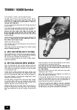
FIG. 12
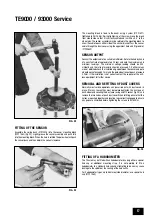
FIG. 13


