background image

12

TE9000 / 93000 Service

17. GREASE CAMSHAFT BEARINGS

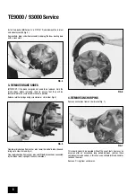
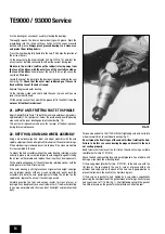
Grease camshaft bearings using grease gun (fig. 14), it is possible to see
the grease extrude from the side plates of the camshaft head bearings
with the hub and drum removed. Ensure the correct specification of
grease is used.

18. INSPECT BRAKE DRUMS

Clean excess brake dust from brake drum and inspect brake drum bore
for surface corrosion, damage and excessive wear.

Remove light corrosion by using coarse emery cloth at an angle of 45
degrees in one direction and then 45 degrees in the other direction to
produce a cross hatch effect, do not use any form of power tool.

If the drum bore shows signs of heat crazing it usually can be reused but
if the heat crazing is severe the drum should be replaced.

It is permissible to machine out the brake drum to a maximum of
Ø423mm. Oversize cam rollers must be fitted if this is done (21006610A).

19. REMOVE OIL SEAL

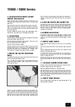
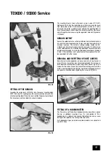
If the oil seal is still within the hub remove it with a work shop pri-bar and
discard it (fig. 15). Take care not to contaminate the inner bearing and hub
cavity.

If the oil seal has remained on the spindle journal lever it off taking great
care not to damage the spindle. Clean the area around the oil seal journal
as detailed in paragraph 6. Discard the oil seal.

Never reuse an oil seal after the hub has been dismounted from the
spindle.

20. WHEEL BEARING INSPECTION AND
GREASING

Step 20a describes the routine inspection and service.

Step 20b should be carried out every 300,000 km, or every 3 years or if
the grease appears dirty, contaminated or burnt, or if no cavity fill is
present.

Refer to grease type and fill volumes specified on page 6.

20a. ROUTINE ANNUAL HUB SERVICE

INNER BEARING:

If the grease within the hub is clean and does not appear or smell burnt
there should be no requirement to totally clean down the assembly and
re-grease the bearings.

Care must be taken not to contaminate the lubricant during the inspection.

Check the hub cavity and inner bearing for contamination caused when
the hub was dismounted from the spindle. Contamination must be
removed and if necessary a total clean down and re-lubrication as
described in step 20b must be performed.

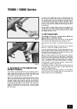
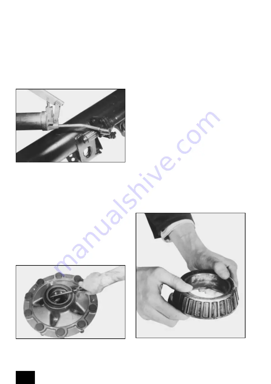
Remove the inner bearing cone (fig. 16) and check the condition of the
grease.

FIG. 14

FIG. 15

FIG. 16

Summary of Contents for 93000 Service

Page 1: ...Meritor Axle Brake Service Manual TE Series Axle ...

Page 2: ...ssemble Anchor Pins Inspect Brake Linings Clean and Assemble Brake Shoes Inspect Brake Springs Inspection of Camshafts and Camshaft Bearings for Play Removal of Camshafts and Camshaft Bearings Replacement of the Camshafts and Camshaft Bearings Refit Brake Shoes Grease Camshaft Bearings Inspect Brake Drums Remove Oil Seal Wheel Bearing Inspection and Greasing Routine Annual Hub Service 3 Year 300 0...

Page 3: ...days from the date of failure and all components involved in the claim must be retained and available for inspection for 90 days from the date of claim being submitted No deductions shall be made from remittances or current accounts in respect of any warranty claims whilst those claims are being processed All claims must quote component Serial Numbers where applicable and relevant vehicle number i...

Page 4: ...Type MX M22 x 1 5p wheel studs for single steel wheels MXA M22 x 1 5p wheel studs for single alloy wheels Table C Axle Nominal Highway Wall Max Series Rating Kg Thickness Offset 90 9300 13mm 460mm 93 9300 16mm 490mm AXLE TYPE APPROVAL No P41ABS15STVZO WREXHAM LL12 0PB UK ASSEMBLED IN THE EEC SERIAL No B999999 G94 0000 NOM CAPACITY 9300Kg V MAX COMB CAPACITY 9300Kg 105KM H T E Anti Lock Type Table ...

Page 5: ...ESSES AND WELDING During use the axle beam is subjected to a wide variety of forces These are caused by the payload bumps in the road surface cornering and braking Because these forces are constantly varying the stresses in the axle beam also vary causing fatigue The top and bottom of the beam generally experience the greatest stresses and hence the most fatigue whilst the section of beam around t...

Page 6: ...ition to the annual inspection a hub bearing assembly grease change is required with careful examination of the bearings and journals also described in SECTION 1 TORQUE RECOMMENDATIONS RECOMMENDED LUBRICANTS Hub cap bolts grease and oil 11 15 Nm Dust cover bolts 50 60 Nm Spherical bearing bolts spline end 50 60 Nm Spherical bearing bolts cam head end 50 60 Nm Sensor fixing bolts GRAU 8 11 Nm Senso...

Page 7: ...ct Brake Springs 13 Inspection of Camshafts and Camshaft Bearings for Play 14 Removal of Camshafts and Camshaft Bearings 15 Replacement of Camshafts and Camshaft Bearings 16 Refit Brake Shoes 17 Grease Camshaft Bearings 18 Inspect Brake Drums 19 Remove Oil Seal 20 Wheel Bearing Inspection and Greasing 20a Routine Annual Hub Service 20b 3 Year Major Hub Service 21 Apply Anti fretting Paste to Spind...

Page 8: ...springs using screwdriver or similar tool fig 5 Free lower brake shoe from anchor pins lower this end of brake shoe and bring up to side of brake fig 6 Free top brake shoe from anchor pins and lift both brake shoes connected by the brake return spring off the anchor bracket 4 REMOVE ANCHOR PINS Remove anchor pins from anchor bracket fig 7 This should normally be possible without the use of tools h...

Page 9: ...shoe Remove the clips from the cam rollers and inspect for damage to the retaining tabs if they have cracked broken off or failed to spring out the clip it must be replaced 8 CLEAN CAM ROLLERS AND ANCHOR PINS The working surfaces of the cam rollers and the anchor pins should be cleaned to remove any build up of compressed debris adhered to the working surfaces In our experience the quickest and ea...

Page 10: ...ng with the bearings with the hub assembly in place using the key hole slot in the anchor bracket to allow the cam head to pass through it To proceed in this manner unfasten the M10 retaining screws securing the head and spline end bearings to the brackets figs 11 and 12 Guiding the head pull the cam head backwards through the slot and pull the camshaft and bearings away from the axle fig 13 Unfas...

Page 11: ...OT TIGHTEN BEARING SECURING SCREWS UNTIL BRAKE SHOES ARE FITTED 16 REFIT BRAKE SHOES If the old linings are to be reused ensure each shoe is returned to its original position as marked prior to removal Either stand both brake shoes on their sides with the cam rollers together and fit the return spring between the roll pins of both brake shoes Lift the top brake shoe the lower shoe will automatical...

Page 12: ...the inner bearing and hub cavity If the oil seal has remained on the spindle journal lever it off taking great care not to damage the spindle Clean the area around the oil seal journal as detailed in paragraph 6 Discard the oil seal Never reuse an oil seal after the hub has been dismounted from the spindle 20 WHEEL BEARING INSPECTION AND GREASING Step 20a describes the routine inspection and servi...

Page 13: ...acing the outer bearing Fit the retaining washer and clip to hold the cone in place ready for re mounting the hub 20B 3 YEAR 300 000 KM MAJOR HUB SERVICE Remove the retaining clip washer inner and outer bearing cones figs 17 and 18 and clean off all grease to inspect the bearings Do not use water steam or air jets to clean the bearings Wipe clean the hub cavity removing all the old grease and any ...

Page 14: ...r bearing is removed be certain to place it in a clean area before it is reassembled in the hub To mount the hub assembly without the outer bearing retaining washer and clip in place push assembly fully onto axle and guard against striking the oil seal on the spindle end replace the oil seal if any damage occurs Fit the outer bearing cone Fit the outer bearing retaining washer with the writing out...

Page 15: ...ES MANUAL SLACK ADJUSTERS Using the manual adjustment nut on the slack adjuster adjust the brake until the wheel can not be turned by hand Back off brake until it is just possible to freely turn the wheel without resistance from the brake linings AUTOMATIC SLACK ADJUSTERS Follow the appropriate setting procedure for the type of automatic slack adjuster fitted Instructions are available through Mer...

Page 16: ...it oil seal end upwards on a clean flat surface and cover the bore with a clean cloth to protect the bearings and grease from contamination Check that the pole wheel mounting spigot on the hub is clean and free from rust using medium emery paper to clean up if necessary Ensure no emery dust or other debris contaminates the bearings or grease The pole wheel 21221064 can be fitted hot or cold using ...

Page 17: ...s and the ratio of max min should not exceed 2 If either values are not obtained check the installed air gap between the sensor and pole wheel does not exceed 0 7mm and the pole wheel runout does not exceed 0 2mm If the installation is not correct contact the supplier of the anti lock equipment for further advice REMOVAL AND REFITTING OF DUST COVERS Normally most service operations can be carried ...

Page 18: ...tyre sizes as shown in fig 26 REMOVAL AND REFITTING OF BRAKE DRUM The brake drum can be separated from the hub after removal of the road wheel as follows Remove the two countersunk drum retaining screws from the drum flange face using a 10mm Allen key fig 27 These screws can then be used to jack the drum free of its locating spigots by refitting them to the two plain tapped holes in the drum flang...

Page 19: ... spigot to locate the pole wheel and axle beams are plain drilled for self tapping bolt to allow the fitting of the sensor mounting block fig 29 It is important that the correct bolt is used FIG 29 E C D B A ITEM DESCRIPTION PART NO A Pole Wheel 21221064 B Sensor Bracket 22221063 C Spring Bush 21213036 D Screw Spring Washer 21221521 E Sensor Assembly 21213034 ...

Page 20: ...Lumière 77290 Mitry Mory France Telephone 33 0 1 64 27 44 61 Fax 33 0 1 64 27 30 45 Meritor HVS Verona s r l Commercial Vehicle Systems Via Monte Fiorino 23 37057 San Giovanni Lupatoto Verona Italy Telephone 39 045 8750399 Fax 39 045 8750640 8750513 Meritor HVS Barcelona S A Commercial Vehicle Systems Ctra Granollers Sabadell Km 13 3 Poligono Argelagues 08185 Lliçà de Vall Spain Telephone 34 9 3 8...

Reviews: