background image

Maintenance Manual MM-0164

Wheel end assembly

Hub Reduction  3 - 4 planets 

- Wheel end with unitized bearing
- Traditional wheel end 

Revised 03-2019  

Summary of Contents for MM-0164

Page 1: ...Maintenance Manual MM 0164 Wheel end assembly Hub Reduction 3 4 planets Wheel end with unitized bearing Traditional wheel end Revised 03 2019 ...

Page 2: ...AUTION A CAUTION indicates a procedure that you must follow exactly to avoid damaging equipment or components Serious personal injury can also occur NOTE A note indicates an operational procedure or instruction that is important for proper service A NOTE can also supply information that will help to make service quicker and easier This symbol indicates that you must tighten fasteners to a specific...

Page 3: ...terference 31 1 Description 32 Exploded view 33 Cross sectional view 34 Parts list 35 Description 36 Tightening torques 36 Lubricants 39 2 Wheel end disassembly 40 Wheel end disassembly 47 Checking and replacing parts 47 3 Wheel end assembly 48 Wheel end assembly 50 Hub assembly 52 Final Clearance calculation pg 55 Part 3 Traditional wheel end with 3 4 planets Spindle fitted with screws 55 1 Descr...

Page 4: ...l operating conditions Operator Any person who will use the wheel end assembly as part of a more complex device Warranty Warranty applies to the wheel end assembly installed on vehicles for which it was designed Warranty is void in the following cases Improper use of the vehicle on which the wheel end assembly is installed usage conditions overloading etc Tampering with vehicle components that may...

Page 5: ...heel end assembly pg 1 Part 1 Hub reduction with 3 4 planets Wheel end with unitized bearing 06 Exploded view 07 Parts list 08 Cross sectional view 09 Parts list 10 Description 11 Tightening torques 11 Lubricants ...

Page 6: ...6 Meritor Wheel end assembly 1 Part 1 Hub reduction with 3 4 planets Wheel end with unitized bearing Exploded view Old version No more applied Old version New version 5 69375 02 ...

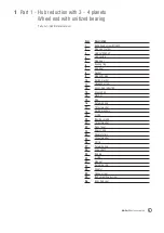
Page 7: ... plug Spring washer Hexagon screw Cover hub reduction Grooved pin Washer Plug Retaining ring Thrust washer Spring washers O ring Bearing spindle Thrust washer Planet gear Spacer ring Needle rollers Thrust washer Circlip Retaining ring Circlips Snap ring Drive shaft Spindle O ring Magnetic washer Star lock push on fastener Locking Screw Inner hub seal 1 2 3 4 5 6 7 8 9 10 11 12 13 14 15 16 17 18 19...

Page 8: ...Solid Hollow shaft 8 Meritor Wheel end assembly 1 Part 1 Hub reduction with 3 4 planets Wheel end with unitized bearing Cross sectional vew Hub Nut Star version ...

Page 9: ...ket Magnetic plug Spring washer Hexagon screw Cover hub reduction Grooved pin Washer Plug Retaining ring Thrust washer Spring washers O ring Bearing spindle Thrust washer Planet gear Spacer ring Needle rollers Thrust washer Circlip Retaining ring Drive shaft Spindle O ring Magnet Retaining clip Adapter Flange screw Bolt socket head screw Inner hub seal 1 2 3 4 5 6 7 8 9 10 11 12 13 14 15 16 17 18 ...

Page 10: ... is jointly to the rear axle spindle by spline fig 1 3 The hub is carried on two tapered roller bearings When the drive shaft and the sun gear rotates the rotation is transmitted to the planets gears Because the ring gear is fixed to the rear axle spindle the planets gears rotate inside the ring gear and the rotation movement is transmitted to the hub assy Ratio formula 1 Z Ring gear Z Sun teeth f...

Page 11: ...als WARNING Only original Meritor spare parts should be used Use of non recommended lubricants will adversely affect performance and service life Use of non original parts could seriously affect wheel end assembly performance Fig 1 5a Fig 1 5b Torque chart specifications and data Hub gear Type cylindrical planetary gear Designation 3 or 4 Planets 19 teeth Ratio 3 46 1 1 64 26 3 46 Ratio 3 33 1 1 6...

Page 12: ...e Oil level indicator Hollow shaft Fig 1 9 Filler plug Top up oil until starts to come out of filler hole Oil level indicator Solid shaft Hub reduction Magnet location Fig 1 7 Hub reduction Magnet location Hub Reduction Magnets Lubricant 1 Part 1 Hub reduction with 3 4 planets Wheel end with unitized bearing ...

Page 13: ...13 Meritor Wheel end assembly pg 2 Part 1 Wheel end disassembly 14 Disassembly 16 Star hub nut dismantling 19 Checking and replacing parts ...

Page 14: ...s recommendations and drain the oil from the axle s Fig 2 2 Remove the hub drain plug and discard Drain oil from wheel end Fig 2 3 Tighten in dedicated holes the tool s screws equally and simultaneously and avoid using excessive force as this could damage the drum Fig 2 4 A soft faced mallet may be used on the drum to loosen and ease withdraw Fig 2 1 Fig 2 2 Fig 2 3 Fig 2 4 2 Part 1 Hub reduction ...

Page 15: ...ws with suitable sized wrench and remove the hub cover from the end of the hub casing Fig 2 5 Remove the retaining ring sun gear and spring washers from axle shaft Fig 2 6 Remove the 2 sunk head screws M10X25 Fig 2 7 Remove the hub casing group and remove axle shaft Fig 2 8 Fig 2 6 Fig 2 5 Fig 2 7 Fig 2 8 Retaining ring Sun gear ...

Page 16: ... shear the staking points and a torque multiplication device should be employed Fig 2 10 Remove the hub nut and discard Star hub nut dismantling Remove locking screw and discard Unscrew the hub retaining nut and discard Fig 2 11 Nut cannot be reused because the anti friction coating on the hub nut face maybe damaged NOTE A high torque is required to release the nut therefore a torque multiplicatio...

Page 17: ...ssembly Fig 2 13 WARNING Do not reuse this seal Remove the outer O ring from the hub and discard Fig 2 14 Remove the drive shaft seal by levering out and discard Fig 2 15 WARNING Do not reuse this seal Hub bearings are pre adjusted cartridge type and cannot be individually replaced In case of non serviceability a replacement service exchange hub should be refitted O Ring Fig 2 15 ...

Page 18: ...move the planet gears washers and needle rollers Fig 2 17 Remove the O ring seals from the journal pins and discard Fig 2 18 WARNING Do not reuse these O Ring seals as old seals cannot protect against oil leaks when rebuilt Remove the ring gear locking ring internal circlip and separate the ring gear from its carrier Fig 2 19 2 Part 1 Hub reduction with 3 4 planets Wheel end with unitized bearing ...

Page 19: ... in the gears with the spacer sleeve Fig 2 20 NOTE each gear must have 38 needle rollers Place the planets gears and thrust washers in the hub casing aligning with the journal pin bore and ensuring that the brass washers are in contact with the hub casing Fit new O rings on the journal pins and grease thoroughly with GLEITMO 805 grease Press in the journal pins using a drift The pins should be pre...

Page 20: ...20 Meritor Wheel end assembly ...

Page 21: ...21 Meritor Wheel end assembly pg 3 Part 1 Wheel end assembly 22 Seal Assembly 26 Hub asssembly 28 Final Clearance calculation ...

Page 22: ... bore in the right position i e with spring s lip toward the spindle or external to the tool Fig 3 2 Press the seal into the spindle bore Fig 3 3 The tool through its shape drives the seal into the spindle leaving the proper seal protrusion avoiding any seal distortion Fig 3 4 3 Part 1 Hub reduction with 3 4 planets Wheel end with unitized bearing Fig 3 4 Spring Lip Protrusion ...

Page 23: ...g Fig 3 5 O Ring Refit a new outer O ring on the hub using grease as lubricant Fig 3 5 Refit the hub assembly Thoroughly grease the spindle bearing journals and locate the hub in position on the spindle Locate the ring gear carrier into position Fig 3 6 Assembly ring gear group Fig 3 7 Fig 3 6 Fig 3 7 ...

Page 24: ...nd with unitized bearing WARNING Always use a new star Hub Nut Fig 3 8 Original nut cannot be used because the anti friction coating on the hub nut face may be damaged Tighten hub nut to 150 30 Nm Rotate hub 20 revolutions Tighten hub nut to 1200 120 Nm Fig 3 8 Star Nut Fig 3 9 ...

Page 25: ...ed bearing Fig 3 11 Fig 3 10 Star Nut Fit new locking patch screw to one of the six thread holes that allows the cap screw head to sit into one of the slots in the nut flange Fig 3 10 Do not clamp the nut flange under the head of the locking screw Tighten screw to 45 5 Nm WARNING see fig 3 11 ...

Page 26: ...l circlip Fig 3 12 Fit the hub casing onto the hub ensuring that the hub external O ring is thoroughly lubricated using hub oil Fig 3 13a Retain the hub casing in position with two socket bolts using thread locking compound Loctite 243 Fig 3 13b Tighten bolts to a torque of 40 10 Nm Fig 3 14 3 Part 1 Hub reduction with 3 4 planets Wheel end with unitized bearing ...

Page 27: ... axle shaft are completely pressed in Fig 3 15 Dimension A With the depth slide gauge measure the distance between the sun gear thrust washers and the face of the hub casing Fig 3 16 Record Dimension A mm Fig 3 17a Pull out the sun gear approximately 10 mm Fig 3 17b Fig 3 16 Fig 3 17a Dim A Fig 3 17b Thrust washer Face Hub Casing Face Hub Casing Sun Gear completely pressed Dim A Face Hub Casing Su...

Page 28: ...de gear Final Clearance calculation Dimensions A B between 1 2 mm Fig 3 18 If outside these limits remove the grooved pin and change the number of washers under the pin Fig 3 19 Refit the magnetic washer over the grooved pin and retain in position with a new star lock fastener Fig 3 20 Washers Debris Magnet in Hub Reduction Unit Final Clearance from 1 to 2 mm Position referred Dim A Position refer...

Page 29: ...ponents must be assembled immediately to permit the silicone gasket material to compress evenly between the mating surfaces Refit the cover plate on the end of the hub casing and retain with screws Torque 20 5Nm Fig 3 22 Fill hub with 2 5 litres of oil as specified by vehicle manufacturer Fit new oil drain plug Torque 80Nm 20Nm Fig 3 23 Hollow shaft Fig 3 24 Solid shaft NOTE with new hub cap there...

Page 30: ...30 Meritor Wheel end assembly ...

Page 31: ...r Wheel end assembly pg 1 Part 2 Traditional wheel end with 3 4 planets Spindle fitted with interference 32 Exploded view 33 Cross sectional view 34 Parts list 35 Description 36 Tightening torques 36 Lubricants ...

Page 32: ...32 Meritor Wheel end assembly 1 Part 2 Traditional wheel end with 3 4 planets Spindle fitted with interference Exploded view ...

Page 33: ...33 Meritor Wheel end assembly 1 Part 2 Traditional wheel end with 3 4 planets Spindle fitted with interference Cross sectional view ...

Page 34: ...t Wheel Bearing Ring Gear Retaining ring Hub case Gear planet Needle Spacer ring Thrust washer steel Thrust washer brass Bearing spindle O ring Retainer clip Sun gear Spring washer Thrust washer Retainer clip Washers Pin Magnet Retain clip Hub cover screw Plug Magnet Gasket copper washer Cover Screw Abs bracket optional Bolts optional Sensor assy optional 1 2 3 4 5 6 7 8 9 10 11 12 13 14 15 16 17 ...

Page 35: ... gear is jointly to the rear axle spindle by spline fig 1 3 The hub is carried on two tapered roller bearings When the drive shaft and the sun gear rotates the rotation is transmitted to the planets gears Because the ring gear is fixed to the rear axle spindle the planets gears rotate inside the ring gear and the rotation movement is transmitted to the hub assy Ratio formula 1 Z Ring gear Z Sun te...

Page 36: ...se of non recommended lubricants will adversely affect performance and service life Use of non original parts could seriously affect wheel end assembly performance Fig 1 5a Fig 1 5b Torque chart specifications and data Hub gear Type Cylindrical planetary gear Designation 3 or 4 Planets 19 teeth Ratio 3 46 1 1 64 26 3 46 Ratio 3 33 1 1 63 27 3 33 Tightening torques Pos Tightening torques Nm 28 Hub ...

Page 37: ... wheel end with 3 4 planets Spindle fitted with interference Fig 1 6 Fig 1 7 Filler plug Top up oil until starts to come out of filler hole Oil level indicator Solid shaft Hub reduction Magnet location Fig 1 8 Hub reduction Magnet location Description ...

Page 38: ...38 Meritor Wheel end assembly ...

Page 39: ...39 Meritor Wheel end assembly pg 2 Part 2 Wheel end disassembly 40 Wheel end disassembly 47 Checking and replacing parts ...

Page 40: ... in the inside wheel Jack up the rear axle of the vehicle to vehicle manufacturers recommendations and drain the oil from the axle s Fig 2 2 Remove the hub drain plug and discard Drain oil from wheel end Fig 2 3 Tighten in dedicated holes the tool s screws equally and simultaneously and avoid using excessive force as this could damage the drum Fig 2 4 A soft faced mallet may be used on the drum to...

Page 41: ...screws with suitable sized wrench and remove the hub cover from the end of the hub casing Fig 2 5 Remove the retaining ring sun gear and spring washers from axle shaft Fig 2 6 Remove the 2 sunk head screws M10X25 Fig 2 7 Remove the hub casing group and remove axle shaft Fig 2 8 Fig 2 6 Fig 2 5 Fig 2 7 Fig 2 8 Retaining ring Sun gear ...

Page 42: ...erence 1 Use a punch to remove locking indent on wheel hub nut collar Fig 2 9 2 Undo the nut using a wrench Remove the hub nut and discard Fig 2 10 3 Remove the ring gear group Fig 2 11 NOTE If available use a lifting tool WARNING Do not damage the thread of the wheel end spindle Fig 2 9 Fig 2 10 Fig 2 11 ...

Page 43: ...4 Remove the external wheel bearing Fig 2 12 5 Remove the hub Fig 2 13 and check the green o ring in the back side Fig 2 14 NOTE If available use a lifting tool WARNING Do not damage the thread of the wheel end spindle WARNING If the green o ring has a mark discard and scrap it Fig 2 13 Fig 2 12 Fig 2 14 O Ring ...

Page 44: ...re below otherwise move to point 10 7 Disconnect ABS sensor cable completely and remove it 8 Untighten the brackets Fig 2 15 9 If needed replace the ABS sensor Figg 2 16 2 17 Fig 2 15 Fig 2 16 Fig 2 17 2 Part 2 Traditional wheel end with 3 4 planets Spindle fitted with interference ...

Page 45: ... planets version showed Press out the journal pins using a suitable drift Remove the planet gears washers and needle rollers Fig 2 19 Remove the O ring seals from the journal pins and discard Fig 2 20 WARNING Do not reuse these O Ring seals as old seals cannot protect against oil leaks when rebuilt Remove the ring gear locking ring internal circlip and separate the ring gear from its carrier Fig 2...

Page 46: ...the gears with the spacer sleeve Fig 2 22 NOTE each gear must have 38 needle rollers Place the planets gears and thrust washers in the hub casing aligning with the journal pin bore and ensuring that the brass washers are in contact with the hub casing Fit new O rings on the journal pins and grease thoroughly with GLEITMO 805 grease Press in the journal pins using a drift The pins should be pressed...

Page 47: ...eritor Wheel end assembly 2 Part 2 Traditional wheel end with 3 4 planets Spindle fitted with interference pg 3 Part 2 Wheel end assembly 48 Wheel end assembly 50 Hub assembly 52 Final Clearance calculation ...

Page 48: ...e spindle bearing journals and locate the hub in position on the spindle without the external bearing Fig 3 2 NOTE If available use a lifting tool WARNING Do not damage the thread of the wheel end spindle 3 Fit the external wheel bearing Fig 3 3 4 Locate the ring gear carrier into position Assembly ring gear group Fig 3 4 3 5 Fig 3 2 Fig 3 4 Fig 3 3 Fig 3 1 O Ring 3 Part 2 Traditional wheel end wi...

Page 49: ...osition and retighten it If nut turns repeat previous step until nut no longer turns when retightened Use a torque wrench on wheel end The torque of the new nut wheel should be 64 20Nm Fig 3 6 Alternative method applied as shown in the picture here below In this test modality the linear force range should be 10 28N Fig 3 7 NOTE If the torque is outside the spec return at the previous point and rea...

Page 50: ... 9 Hub assembly Fit the sun gear with spring washers and thrust washer and retain with an internal circlip Fig 3 10 Fit the hub casing onto the hub ensuring that the hub external O ring is thoroughly lubricated using hub oil Fig 3 11 Retain the hub casing in position with two socket bolts using thread locking compound Loctite 243 Fig 3 12 Tighten bolts to a torque of 40 10 Nm Fig 3 13 Fig 3 11 ...

Page 51: ...d the axle shaft are completely pressed in Fig 3 14 Dimension A With the depth slide gauge measure the distance between the sun gear thrust washers and the face of the hub casing Fig 3 15 Record Dimension A mm Fig 3 16a Pull out the sun gear approximately 10 mm Fig 3 16b Fig 3 15 Fig 3 16a Dim A Fig 3 16b Thrust washer Face Hub Casing Face Hub Casing Sun Gear completely pressed Dim A Face Hub Casi...

Page 52: ...ar thrust washer as previously record dimension B mm Fig 3 16c with depth slide gear Final Clearance calculation Dimensions A B between 1 2 mm Fig 3 17 If outside these limits remove the grooved pin and change the number of washers under the pin Fig 3 18 Refit the magnetic washer over the grooved pin and retain in position with a new star lock fastener Fig 3 19 Washers Debris Magnet in Hub Reducti...

Page 53: ...he components must be assembled immediately to permit the silicone gasket material to compress evenly between the mating surfaces Refit the cover plate on the end of the hub casing and retain with screws Torque 20 5Nm Fig 3 21 Fill hub with 2 5 litres of oil as specified by vehicle manufacturer Fit new oil drain plug Torque 80Nm 20Nm Fig 3 22 Solid shaft NOTE with new hub cap there is an oil level...

Page 54: ...54 Meritor Wheel end assembly ...

Page 55: ...itor Wheel end assembly pg 1 Part 3 Traditional wheel end with 3 4 planets Spindle fitted with screws 56 Exploded view 57 Cross sectional view 58 Parts list 59 Description 60 Tightening torques 60 Lubricants ...

Page 56: ...56 Meritor Wheel end assembly 1 Part 3 Traditional wheel end with 3 4 planets Spindle fitted with screws Exploded view ...

Page 57: ...57 Meritor Wheel end assembly 1 Part 3 Traditional wheel end with 3 4 planets Spindle fitted with screws Section view ...

Page 58: ...heel Bearing Ring Gear Retaining ring Hub case Gear planet Needle Spacer ring Thrust washer steel Thrust washer brass Bearing spindle O ring Retainer clip Sun gear Spring washer Thrust washer Retainer clip Washers Pin Magnet Retain clip Hub cover screw Plug Magnet Gasket copper washer Cover Screw Abs bracket optional Bolts optional Sensor assy optional 1 2 3 4 5 6 7 8 9 10 11 12 13 14 15 16 17 18 ...

Page 59: ...ar is jointly to the rear axle spindle by spline fig 1 3 The hub is carried on two tapered roller bearings When the drive shaft and the sun gear rotates the rotation is transmitted to the planets gears Because the ring gear is fixed to the rear axle spindle the planets gears rotate inside the ring gear and the rotation movement is transmitted to the hub assy Ratio formula 1 Z Ring gear Z Sun teeth...

Page 60: ...nded lubricants will adversely affect performance and service life Use of non original parts could seriously affect wheel end assembly performance Fig 1 5a Fig 1 5b Torque chart specifications and data Hub gear Type Cylindrical planetary gear Designation 3 or 4 Planets 19 teeth Ratio 3 46 1 1 64 26 3 46 Ratio 3 33 1 1 63 27 3 33 Tightening torques Pos Tightening torques Nm Wheel end screws 225 20 ...

Page 61: ...art 3 Traditional wheel end with 3 4 planets Spindle fitted with screws Fig 1 6 Fig 1 7 Filler plug Top up oil until starts to come out of filler hole Oil level indicator Solid shaft Hub reduction Magnet location Description Lubricant ...

Page 62: ...62 Meritor Wheel end assembly ...

Page 63: ...63 Meritor Wheel end assembly pg 2 Part 3 Wheel end disassembly 64 Wheel end disassembly ...

Page 64: ...rers recommendations and drain the oil from the axle s Fig 2 2 Remove the hub drain plug and discard Drain oil from wheel end Fig 2 3 Tighten in dedicated holes the tool s screws equally and simultaneously and avoid using excessive force as this could damage the drum Fig 2 4 A soft faced mallet may be used on the drum to loosen and ease withdraw Fig 2 1 Fig 2 2 Fig 2 3 Fig 2 4 2 Part 3 Traditional...

Page 65: ... hub casing Fig 2 5 Remove the retaining ring sun gear and spring washers from axle shaft Fig 2 6 Remove the 2 sunk head screws M10X25 Fig 2 7 Remove the hub casing group and remove axle shaft Fig 2 8 Fig 2 6 Fig 2 5 Fig 2 7 Fig 2 8 Retaining ring Sun gear 2 Part 3 Traditional wheel end with 3 4 planets Spindle fitted with screws ...

Page 66: ...nut collar Fig 2 9 2 Undo the nut using a wrench Remove the hub nut and discard Fig 2 10 3 Remove the ring gear group Fig 2 11 NOTE If available use a lifting tool WARNING Do not damage the thread of the wheel end spindle 4 Remove the external wheel bearing Fig 2 12 WARNING Do not damage the thread of the wheel end spindle Fig 2 9 Fig 2 10 Fig 2 11 Fig 2 12 ...

Page 67: ... lifting tool WARNING Do not damage the thread of the wheel end spindle WARNING If the green o ring has a mark discard and scrap it 6 If the axle has an ABS sensor proceed as shown here below otherwise move to point 10 7 Disconnect ABS sensor cable completely and remove it 8 Untighten the brackets Fig 2 15 9 If needed replace the ABS sensor Figg 2 16 2 17 Fig 2 13 Fig 2 15 Fig 2 16 Fig 2 17 Fig 2 ...

Page 68: ...t to use any electric or pneumatic screwdrivers TIP TRICK to ease assembly and adjustment procedures mark the position of the lever on the camshaft TIP TRICK Just as before mark the position of the clevis on the air chamber pushrod to help yourself during the a NOTE For further instructions on the brake setting adjustment and operation refer to service manual MM0267 ssembly and adjustment procedur...

Page 69: ...ushrod M10x1 5 Discard Scrap the nut 12 Remove the lever Fig 2 22 13 Remove the brake and the spindle Fig 2 23 14 Untighten and remove the brake from the spindle Screw M16x2 Discard Scrap the screw Fig 2 24 WARNING To avoid any problems on the thread it is advised not to use any electric or pneumatic screwdrivers If the green o ring has a mark discard and scrap it Fig 2 21 Fig 2 22 Fig 2 23 Fig 2 ...

Page 70: ...ut of the housing and falling accidentally 16 The spacer if present is free and it s possible to remove it Do not remove the stud NOTE Scrap the original o ring and fit a new one in the spindle and in the spacer if it was disassembled NOTE Do not remove the three studs from the housing The studs will be needed during the reassembly procedure NOTE Check the threads on the housing Use air flow to cl...

Page 71: ...71 Meritor Wheel end assembly pg 3 Part 3 Wheel end assembly 72 Wheel end assembly 78 Hub assembly 80 Final Clearance calculation ...

Page 72: ... of hub and axle shaft have been cleaned thoroughly 1 Tighten the stud on the axle Fig 3 1 2 Assembly the new o ring in the slot of the spacer Fig 3 2 3 Apply grease on the joint surface Fig 3 3 4 Put the spacer if needed according to the axle variant in position Fig 3 4 WARNING Do not damage the o ring present in the spacer Fig 3 1 Fig 3 2 Fig 3 4 Fig 3 3 ...

Page 73: ...tted with screws 5 Assembly the new o ring in the slot of the wheel end Fig 3 5 6 Apply grease on the joint surface Fig 3 6 7 Put the wheel end in the position Fig 3 7 WARNING Do not damage the o ring present in the spacer 8 Put the brake in position Fig 3 8 Fig 3 5 Fig 3 6 Fig 3 7 Fig 3 8 ...

Page 74: ...sert the lever in correspondence of the previously marked done Fig 3 10 11 Insert the clevis in correspondence of the previously marked done Fig 3 11 12 If needed adjust the lever position but do not close the new screw yet Fig 3 12 13 If needed adjust the clevis position on the air chamber pushrod but do not close the new screw yet Fig 3 13 Fig 3 9 Fig 3 10 Fig 3 11 Fig 3 13 Fig 3 12 ...

Page 75: ...el should be 225 20Nm 15 Tighten the new screws of L brackets with a torque wrench The torque of the new screw wheel should be 175 25Nm Fig 3 15 16 Tighten the lever pinch bolt nut The torque of the new nut wheel should be 55 75Nm Fig 3 16 17 Tighten the lever on the camshaft The torque of the new screw wheel should be 48 8 Nm Fig 3 17 18 Refit a new outer O ring on the hub using grease as lubrica...

Page 76: ...ate bracket Fig 3 19 21 Fit the bracket with the sensor in place Fig 3 20 22 Apply the appropriate brackets to guarantee the correct passages to the ABS cable Fig 3 21 23 Thoroughly grease the spindle bearing journals and locate the hub in position on the spindle without the external bearing Fig 3 22 NOTE If available use a lifting tool WARNING Do not damage the thread of the wheel end spindle 24 ...

Page 77: ...at previous step until nut no longer turns when retightened Use a torque wrench on wheel end The torque of the new nut wheel should be 64 20Nm Fig 3 25 Alternative method applied as present in the picture here below In this test modality the linear force range should be 10 28N Fig 3 26 NOTE If the torque is outside the spec return at the previous point and readjust it 27 When the wheel end torque ...

Page 78: ... assembly Fit the sun gear with spring washers and thrust washer and retain with an internal circlip Fig 3 29 Fit the hub casing onto the hub ensuring that the hub external O ring is thoroughly lubricated using hub oil Fig 3 30 Retain the hub casing in position with two socket bolts using thread locking compound Loctite 243 Fig 3 31 Tighten bolts to a torque of 40 10 Nm Fig 3 32 Fig 3 30 ...

Page 79: ... slide gauge measure the distance between the sun gear thrust washers and the face of the hub casing Fig 3 34 Record Dimension A mm Fig 3 35a Pull out the sun gear approximately 10 mm Fig 3 35b Fig 3 34 Fig 3 35a Dim A Fig 3 35b Thrust washer Face Hub Casing Face Hub Casing Sun Gear completely pressed Dim A Face Hub Casing Sun Gear Pull out Pull out 10mm 3 Part 3 Traditional wheel end with 3 4 pla...

Page 80: ...e gear Final Clearance calculation Dimensions A B between 1 2 mm Fig 3 36 If outside these limits remove the grooved pin and change the number of washers under the pin Fig 3 37 Refit the magnetic washer over the grooved pin and retain in position with a new star lock fastener Fig 3 38 Washers Debris Magnet in Hub Reduction Unit Final Clearance from 1 to 2 mm Position referred Dim A Position referr...

Page 81: ...omponents must be assembled immediately to permit the silicone gasket material to compress evenly between the mating surfaces Refit the cover plate on the end of the hub casing and retain with screws Torque 20 5Nm Fig 3 40 Fill hub with 2 5 litres of oil as specified by vehicle manufacturer Fit new oil drain plug Torque 80Nm 20Nm Fig 3 41 Solid shaft NOTE with new hub cap there is an oil level lin...

Page 82: ...82 Meritor Wheel end assembly ...

Page 83: ...83 Meritor Wheel end assembly pg 4 Troubleshooting and Service Tools 86 Troubleshooting 87 Service tools ...

Page 84: ...ecks Oil loss coming from hub outwards Check hub nut Follow instructions from vehicle manufacturer Actions Required Remove wheel end assembly and replace bearing and any other damaged parts Remove hub cover and correctly reapply sealant Check the driveshaft and hub for integrity and that they are in working order Check bearings for integrity Ensure hub nut is correctly tightened Ensure correct tig...

Page 85: ...85 Meritor Wheel end assembly 4 Troubleshooting and Service Tools Mounting tool ...

Page 86: ...Meritor HVS Cameri S p A Strada Prov Cameri Bellinzago km 5 Printed in Italy 28062 Cameri NO Italy Tel 39 0321 4231 Revised 3 2019 Fax 39 0321 423424 www meritor com Meritor 2012 M graph MM0164 ...

Reviews: