background image

Copyright Meritor, Inc., 2021

MM-96147  /  Revised 03-21

Page 1

(16579)
Printed in USA

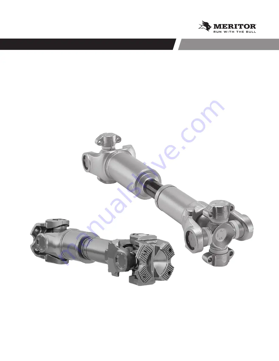
DRIVELINE MAINTENANCE MANUAL

MAINTENANCE MANUAL MM-96147

Summary of Contents for MM-96147

Page 1: ...Copyright Meritor Inc 2021 MM 96147 Revised 03 21 Page 1 16579 Printed in USA DRIVELINE MAINTENANCE MANUAL MAINTENANCE MANUAL MM 96147...

Page 2: ...n Demand on meritor com to access and order additional information Contact the Meritor OnTrac Customer Service Center at 866 668 7221 US and Canada between 7 30 AM and 10 00 PM ET Monday through Frida...

Page 3: ...Round 43 Removal 43 Disassembly 43 Installation 44 Lubrication 46 Section 7 Wing Style Permalube 48 Removal 48 Installation 48 Lubrication 49 Section 8 Easy Service 50 Removal 50 Disassembly 50 Assemb...

Page 4: ...Copyright Meritor Inc 2021 MM 96147 Revised 03 21 Page 4 16579 Printed in USA...

Page 5: ...ation and diagnostics guidelines 4 Use special tools when required to help avoid serious personal injury and damage to components Hazard Alert Messages Read and observe all hazard alert messages in th...

Page 6: ...y the splined shaft points forward in the vehicle For a typical interaxle driveline refer to Figure 2 3 TRANSMISSION TYPICAL DRIVELINE SYSTEM NOTE Series shown are for illustration only NON SLIP COUPL...

Page 7: ...followed by a standard slip drive shaft assembly The non slip coupling shafts are always positioned in front of the slip shaft Figure 2 2 TRANSMISSION TYPICAL THREE SHAFT STANDARD SLIP STANDARD SLIP A...

Page 8: ...rivelines 4003528a SHAFT YOKE END YOKE OUTPUT BEARING CUPS TRUNNION BEARING CROSS END YOKE OUTPUT END YOKE OUTPUT REAR AXLE FRONT AXLE SEAL SLIP YOKE SHORT COUPLED SLIP ASSEMBLY UNIVERSAL JOINT COMPON...

Page 9: ...2 RPL35 and RPL35SD series drivelines are the same as RPL20 RPL25 and RPL25SD series drivelines except they are larger and have coupling anges instead of yokes Figure 3 3 4018229a RPL10 AND RPL14 PER...

Page 10: ...Copyright Meritor Inc 2021 MM 96147 Revised 03 21 Page 10 16579 Printed in USA 3 Introduction EASY SERVICE 1 2 ROUND 4001789a Fig 3 6 WING STYLE 4003527a Fig 3 7 4001789b 155R SERIES Fig 3 8...

Page 11: ...ial movement bent driveline tubing or missing plugs in the slip yoke can damage universal joints and bearings 3 Check the output and input end yokes on both the transmission and axle for axial loosene...

Page 12: ...ve an excessive amount of metal These conditions can damage the cross and bearing and cause the driveline to separate from the vehicle Serious personal injury and damage to components can result 4 Ins...

Page 13: ...yoke or ange retaining nut to 450 600 lb ft 612 816 Nm 4001797a Fig 4 7 Yoke Style Driveline 4011831a GAP NUT Fig 4 8 Flange Style Driveline 2 Inspect the center bearing bracket bolts for looseness Fi...

Page 14: ...aligning center bearing by the bright gold color of the integral de ector De ectors are integral to a self aligning center bearing so separate de ectors are not required Most vehicles are equipped wi...

Page 15: ...00 miles 240 000 km In addition to the 25 000 mile 40 000 km requirements Use the following steps to inspect the slip splines for wear backlash and for radial looseness between the slip yoke and the t...

Page 16: ...f capscrews are missing Check for damage to the universal joint and yoke Replace damaged parts and missing capscrews If capscrews are loose Remove and discard loose capscrews Replace them with new cap...

Page 17: ...ght Meritor Inc 2021 MM 96147 Revised 03 21 Page 17 16579 Printed in USA 4 Inspection 4011832a Fig 4 15 Flange Style Driveline 4001806a Fig 4 16 Yoke Style Driveline 4011832b Fig 4 17 Flange Style Dri...

Page 18: ...t grade new bearing retainer bolts and stamped strap bolts Do not reuse these parts If the bearing retainer straps are damaged install new retainers Damaged and reused parts can affect driveline opera...

Page 19: ...damage to components and serious personal injury 1 Place the universal joint in a suitable press bridge and bearing cup bushing receiver Figure 5 3 4001812c PRESS BEARING CUP BUSHING RECEIVER BRIDGE F...

Page 20: ...4001824a SHROUD Fig 5 9 Assembly Standard Slip Con guration 1 Remove the grease ttings from the slip yoke before you assemble the slip yoke and spline shaft sections 2 Use the grease packet supplied w...

Page 21: ...o the slip yoke until the splines fully engage Figure 5 14 8 Snap the seal into the groove Figure 5 15 SEAL 4001831b Fig 5 15 9 Snap the shroud over the seal Figure 5 16 4018246a SHROUD Fig 5 16 10 Pu...

Page 22: ...CAUTION You must fully seat the snap ring into the snap ring groove to avoid damage to the driveline 4 Use snap ring pliers to install the snap ring into the snap ring groove Figure 5 20 Fully seat t...

Page 23: ...d end of this section DANGER Park the vehicle on a level surface Block the wheels to prevent the vehicle from moving Support the vehicle with safety stands NEVER work under a vehicle supported only by...

Page 24: ...Figure 5 25 4001808b Fig 5 25 3 Remove the capscrews Figure 5 26 4001809b Fig 5 26 NOTE Support the driveline when you remove it from the end yoke 4 If necessary use an appropriate tool to tap the wi...

Page 25: ...ersal joint puller DANGER Observe all warnings and cautions provided by the press manufacturer to avoid damage to components and serious personal injury Method Using a Press Bridge Tool and Bearing Cu...

Page 26: ...Tiger Tool number 10102 Refer to the Service Notes page on the front inside cover of this manual for information to obtain this tool Figure 5 34 BUSHING UNIVERSAL JOINT PULLER TIGERTOOL NUMBER 10102...

Page 27: ...40 Assembly Slip Yoke 1 Use the grease packet supplied with the slip yoke to apply the entire amount of grease into the slip yoke Figure 5 41 4001826b Fig 5 41 2 Use a brush to distribute lubricant o...

Page 28: ...e shroud over the seal Figure 5 47 SHROUD SEAL 4001832c Fig 5 47 9 Push together the driveline sections Figure 5 48 4001834c Fig 5 48 Installation Wing Bushings WARNING If you do not correctly install...

Page 29: ...TALLATION INTERFERENCE BOSS INTERFERENCE BOSS INTERFERENCE BOSS INTERFERENCE BOSS 4003386b Fig 5 49 The previous design wing bushing did not have an interference boss As a result it was possible to in...

Page 30: ...SAL JOINT CROSS At installation the wing bearing weld strap must face INBOARD Align yoke nib with square button on universal joint kit as shown Install the universal joint kit by inserting both of the...

Page 31: ...ugh the yoke bore Figure 5 54 4001886c WING BUSHING ROUND BUSHING Thread the cross through the yoke bore then start the round bushing on the trunnion Fig 5 54 DANGER Observe all warnings and cautions...

Page 32: ...58 Fully seat the snap ring 4001815c WING BUSHING Fig 5 58 7 Position the second bushing onto the trunnion by threading the cross through the yoke bore as shown Figure 5 59 4001816c Thread the trunni...

Page 33: ...nt weld strap faces the driveline and AWAY from the yoke CAUTION A broken weld strap can cause a wing bushing to rotate When a bushing rotates it s possible to assemble it into the yoke backward To en...

Page 34: ...a part can break off Serious personal injury and damage to components can result WARNING Only install the correct grade new bearing retainer bolts and stamped strap bolts Do not reuse these parts If...

Page 35: ...the snap ring can be dislodged from the groove easier 4011725a SNAP RING Fig 5 67 2 Repeat the previous step on the other side of the drive ange 3 Install a press bridge tool SPX ICM Kent Moore tool n...

Page 36: ...f the drive ange and use a press to press DOWN Figure 5 74 4011732a Fig 5 74 10 Remove the half round sleeves from the trunnion and remove the bushing bearing assembly from the receiver 11 Install the...

Page 37: ...755a BRIDGE TOOL TRUNNION Fig 5 79 3 Press DOWN to press the cross free 4 Rotate the drive ange 180 degrees to the other end Install the press bridge tool and press DOWN 5 Install half moons on the to...

Page 38: ...Fig 5 83 3 Install the cross into the drive ange Figure 5 84 4011758a BUSHING CROSS DRIVE FLANGE Fig 5 84 4 Install the bushing on top of the cross and drive ange CAUTION Ensure the universal joint an...

Page 39: ...762a SNAP RING DRIFT HAMMER Fig 5 88 4011773a INCORRECTLY SEATED CORRECTLY OEM SNAP RING SEATED 0 450 11 4 MM MIN LESS THAN 0 450 11 4 MM Fig 5 89 4011773b INCORRECTLY SEATED CORRECTLY SEATED 0 450 11...

Page 40: ...ng bearing assembly DOWN Make sure the yoke is level so the bushing will be pressed straight down Figure 5 96 4011768a PRESS BUSHING CROSS Fig 5 96 6 Tap on the ears of the yoke and move the cross to...

Page 41: ...freely Coupling Joint Flange 1 Use a suitable xture or method to immobilize the drive ange end so the coupling joint end will not rotate 2 Install the coupling joint ange onto the driveline 3 Install...

Page 42: ...washers to secure the coupling joint ange to the vehicle rear drive ange Figure 5 103 Due to tight clearances some applications may require the bolt to be inserted from the yoke ange side without a w...

Page 43: ...earing cups 3 Remove the rst bearing cup If necessary use a bearing puller to remove the bearing cup from the yoke bore Figure 6 1 BUSHING UNIVERSAL JOINT PULLER TIGERTOOL NUMBER 10102 4001893a Fig 6...

Page 44: ...re 6 4 4001821a Fig 6 4 4 Pull the slip yoke and slip shaft sections apart Figure 6 5 4001822a Fig 6 5 5 Remove the seal and shroud Figure 6 6 and Figure 6 7 4001823a SEAL Fig 6 6 4001824a SHROUD Fig...

Page 45: ...the yoke bores and onto the universal joint cross trunnions If necessary use a copper or brass hammer to tap the bearing caps until they are fully seated 3 Hand tighten the capscrews through the bear...

Page 46: ...48 51 65 176N 7 00 177 8 3 8 24 38 48 51 65 18N 7 55 191 77 3 8 24 38 48 51 65 YOKE GAUGE TOOL A dimension across yoke ears determines end yoke universal joint series A Identifies driveline series 400...

Page 47: ...u lubricate a slip yoke the splined shaft can be either fully extended or fully collapsed After installation add Meritor speci cation O 634 B NLGI Grade 2 with EP additive to the slip yoke grease ttin...

Page 48: ...t the vehicle with safety stands 2 Loosen and remove the four capscrews from the weld yoke end of the driveline Support the weld yoke end and separate it from the end yoke 3 Loosen and remove the four...

Page 49: ...igure 7 2 6 Repeat Step 1 to Step 5 to install the opposite driveline end Lubrication Universal Joint Wing style universal joints can be greaseable or non greaseable Non greaseable Permalube universal...

Page 50: ...apscrews and bearing straps from the weld yoke end of the driveline Support the weld yoke end and separate it from the end yoke 3 Loosen and remove the capscrews and bearing straps from the slip yoke...

Page 51: ...seal onto the spline shaft neck Ensure that the small diameter side ts onto the splines rst Figure 8 7 LARGE DIAMETER SMALL DIAMETER SHROUD 4001829a Fig 8 7 3 Install the slip shaft into the slip yoke...

Page 52: ...NOTE Capscrews have a lock patch and can be hand tightened only two or three threads 4 Hand tighten the bearing capscrews Use a torque wrench to tighten the capscrews to the speci ed torque Refer to T...

Page 53: ...sen the bearing cup capscrews Add grease until grease purges from the four seals c Tighten the bearing cup capscrews after grease purges If grease still does not purge from all four trunnion seals Rem...

Page 54: ...he weld yoke end of the driveline Support the weld yoke end and separate it from the end yoke 3 Loosen and remove the capscrews and bearing straps from the slip yoke end of the driveline Support the s...

Page 55: ...e the universal joint from the yoke Disassembly Standard Slip Con guration 1 Mark the slip yoke and slip shaft sections to ensure that you reassemble them into their original positions Figure 9 6 Fig...

Page 56: ...e that the small diameter side ts onto the splines rst Figure 9 11 4001829d LARGE DIAMETER SMALL DIAMETER Fig 9 11 5 Align the slip yoke and spline shaft sections with the phasing marks you made on th...

Page 57: ...NGER Observe all warnings and cautions provided by the press manufacturer to avoid damage to components and serious personal injury CAUTION Use an arbor press or universal joint press to install the r...

Page 58: ...roove Figure 9 19 Fig 9 19 8 Strike the yoke ear with a brass or copper hammer to ensure that the universal joint moves freely Figure 9 20 Move the joint with your hand to ensure free movement Fig 9 2...

Page 59: ...steps below New grease must flow at all four seals Fig 9 22 a Move the assembly UP AND DOWN or SIDE TO SIDE while you apply grease gun pressure b Loosen the bearing cup capscrews Add grease until gre...

Page 60: ...ct grade new bearing retainer bolts and stamped strap bolts Do not reuse these parts If the bearing retainer straps are damaged install new retainers Damaged and reused parts can affect driveline oper...

Page 61: ...ve the universal joint from the coupling yoke or ange Discard the universal joint mounting bolts If it s necessary to unseat the bearing cup assemblies Use a rubber hammer to tap on the yoke or ange o...

Page 62: ...e Style Driveline 3 Remove the center bearing bracket bolts Figure 10 8 and Figure 10 9 4001801a Fig 10 8 Yoke Style Driveline 4011835a Fig 10 9 Flange Style Driveline 4 Remove the coupling shaft with...

Page 63: ...Remove and discard the center bearing bracket Figure 10 12 CENTER BEARING BRACKET Fig 10 12 2 Remove and discard the rubber cushion Figure 10 13 Fig 10 13 3 Use a puller to remove the bearing assembly...

Page 64: ...s hammer to install the bearing 4 If a de ector is required on the yoke or ange use a section of tubing and a brass hammer to press the de ector onto the end yoke or ange Use of the tubing will help a...

Page 65: ...pyright Meritor Inc 2021 MM 96147 Revised 03 21 Page 65 16579 Printed in USA 10 Center Bearing Removal and Installation 4001800a Fig 10 20 Yoke Style Driveline 4011835a Fig 10 21 Flange Style Drivelin...

Page 66: ...vice Wing Style and 155R greaseable drivelines require periodic lubrication of the universal joints and slip yoke splines Figure 11 1 and Figure 11 2 LUBE POINT LUBE POINT LUBE POINT FULL ROUND EASY S...

Page 67: ...l de Refer to the grease manufacturer s speci cations for the temperature service limits On Highway Applications where tractor is operated at least 90 on paved road surfaces and up to 10 on gravel dir...

Page 68: ...eet Meritor Speci cation O 634 B NLGI Grade 2 Lithium 12 Hydroxy Stearate with Molybdenum Disul de Amalie All Purpose Grease with Moly L1 2M Exxon 5160 Shell Super Duty Special FF Marathon Maralube Mo...

Page 69: ...ion Flange Fasteners BOLT NUT WASHER M14 x 2 0 133 163 180 220 Description Thread Size Inches Torque Range lb ft Nm RPL20 RPL25 and RPL25SD Series Permalube Capscrews 1 2 20 M14 x 2 0 115 135 155 183...

Page 70: ...GER Excessive looseness across the ends of the universal joint bearing cup assemblies can cause imbalance or vibration in the driveline assembly Imbalance or vibration can cause component wear which c...

Page 71: ...multiple driveline systems remove the slip yoke assembly from the vehicle to check for movement 1 Ensure that the vehicle is on a level surface with its wheels on the ground For single driveline syst...

Page 72: ...d play in universal joints Replace the universal joints Excessive hinging in slip section Replace worn components Welch plug loose or missing in slip yoke Replace the welch plug or slip yoke Worn cent...

Page 73: ...arity Check the universal joint operating angles Reduce the angles if necessary Excessive torque load for universal joint and driveline size Replace with a higher capacity universal joint and drivelin...

Page 74: ...int and driveline Table K Shaft and Tube Condition Cause Correction Shaft support bearing wear Driveline too long for operating speeds Install a two piece driveline with a shaft support bearing Incorr...

Page 75: ...Correction Loose bolts Dirt or foreign material such as paint on mounting pad Check for fretting on the mounting pads or drive tang Surfaces must be free of foreign material and the bushings must be...

Page 76: ...pported only by jacks Jacks can slip and fall over Failure to use a jack stand can result in serious personal injury and damage to components WARNING To prevent eye injury always wear eye protection w...

Page 77: ...pe Refer to the reverse side Maximum Engine RPM Maximum Engine HP Rear Suspension Ride Height Customer Name Phone Fax OEM Model VIN Last 6 digits only Year Unit Date DSM Transmission Angle 1st Driveli...

Page 78: ...ype 1 PARALLEL PARALLEL Type 2 CROSSED PARALLEL Type 3 PARALLEL CROSSED Type 4 CROSSED CROSSED These yokes are aligned These yokes are aligned These yokes are not aligned These yokes are aligned These...

Page 79: ...E Figure 14 6 Type 1 PARALLEL PARALLEL Type 2 CROSSED PARALLEL Type 3 PARALLEL CROSSED Type 4 CROSSED CROSSED These yokes are aligned These yokes are aligned These yokes are not aligned These yokes ar...

Page 80: ...rd the measurements in the First Driveline Angle and Second Driveline Angle boxes on the Data Gathering Worksheet Figure 14 11 1st Driveline Angle 2nd Driveline Angle 4001910a Fig 14 11 Measure the Fo...

Page 81: ...orrect angle Figure 14 16 Fig 14 16 Write your measurement in the Inter Axle Angle box on the Data Gathering Worksheet Figure 14 17 Front Axle Angle Inter Axle Driveline Angle Rear Axle Angle 4001900a...

Page 82: ...asurements for the transmission and the rst driveline Transmission Angle 2 5 First Driveline Angle 1 0 First Joint Angle 1 0 2 5 1 5 NOTE Remember to include the negative sign for negative component a...

Page 83: ...that the vehicle ride height is within speci cation 1 Click on the View Ride Height Measurement And Adjustment Procedures eld 2 Follow the procedures to measure If necessary adjust the vehicle ride h...

Page 84: ...m these lists NOTE The phasing type is not required for angle analysis of one piece driveline con gurations 4 Enter the driveline phasing type Click on the VIEW button next to the Phasing Type eld to...

Page 85: ...les Plan View Tools Needed Tape measure Carpenter s square or straightedge A plumb bob Prepare the Vehicle DANGER Park the vehicle on a level surface Block the wheels to prevent the vehicle from movin...

Page 86: ...enter of the carrier universal joint to the frame rail Use a carpenter s square or other straightedge if needed Figure 14 28 5 The universal joint plan view angle can now be calculated by using Formul...

Page 87: ...14 33 2 Calculate the plan view universal joint angles using Formula 1 Figure 14 34 4005555a Formula 1 Driveline_Length DistanceTrans DistanceAxle Plan_Angle Tan 1 Fig 14 34 4005572b DRIVELINE LENGTH...

Page 88: ...0 25 6 35 MM RECOMMENDED Fig 15 1 Coupling shaft recommended balance weight placements on tube O D 4017040a SLIPYOKE BALANCE WEIGHT SLIPYOKE CASTING FORGING 0 25 6 35 MM RECOMMENDED Fig 15 2 CAUTION S...

Page 89: ...ERSAL JOINT PRESS TIGERTOOL NUMBER 10707 UNIVERSAL JOINT PULLER TIGERTOOL NUMBER 10102 YOKE BEARING CUP INSTALLATIONTOOL ELECTRONIC PROTRACTER SPX KENT MOORE TOOL NUMBER J 38460 A EVA 2 VIBRATION ANAL...

Page 90: ...579 Printed in USA 16 Special Tools Tool Drawings 4011820a R 0 130 3 302 MM 0 081 2 057 MM 0 008 0 203 MM SEE DETAIL Z DETAIL Z SCALE 6 1 15 RPL35 35SD HALF ROUND SLEEVE 2 038 51 765 MM TANGENT 2 10 5...

Page 91: ...in USA 16 Special Tools 4011821a 0 06 1 524 MM X 45 0 06 1 524 MM X 45 5 00 127 MM 2 79 70 866 MM B B R1 77 44 958 MM A A RPL35 35SD BEARING CUP BUSHING RECEIVER 0 12 3 048 MM 0 12 3 048 MM 2 16 54 86...

Page 92: ...3 21 Page 92 16579 Printed in USA 16 Special Tools 0 684 2 2765 2X R 277 1 13 2 015 1 2 13 UNC 2B 1 01 TAP DRILL 1 27 0 75 2X 35 R 30 2X 35 R 30 0 405 0 13 0 05 0 41075 1 00425 0 75 0 75 0 4075 2 015...

Page 93: ...Copyright Meritor Inc 2021 MM 96147 Revised 03 21 Page 93 16579 Printed in USA 16 Special Tools BEARING CUP BUSHING RECEIVER 2 92 A A SECTION A A 2 38 3 5 0 124 1 7 4017046a Fig 16 5...

Page 94: ...Copyright Meritor Inc 2021 MM 96147 Revised 03 21 Page 94 16579 Printed in USA 16 Special Tools 1 762 2 37 0 265 1 00 0 75 YOKE BEARING CUPTOOL 4017047a Fig 16 6...

Page 95: ...ion of the centerlines of two shafts connected by a universal joint Permalube Universal Joint A permanently lubricated and sealed universal joint that does not require regular lubrication Permalube Dr...

Page 96: ...straight line For drivelines outside of the same plane measure the offsets of each joint to the frame Measure joint center to joint center lengths of each shaft Fax this information to OnTrac s Custom...

Page 97: ...e the offsets of each joint to the frame Measure joint center to joint center lengths of each shaft Fax this information to OnTrac s Customer Service Center at 248 435 5580 or call the Center at 866 O...

Page 98: ...Model Assumptions 1 Drivelines are in the same plane The top view shows all drivelines in a straight line For drivelines outside of the same plane measure the offsets of each joint to the frame Measu...

Page 99: ...n the same plane The top view shows all drivelines in a straight line For drivelines outside of the same plane measure the offsets of each joint to the frame Measure joint center to joint center lengt...

Page 100: ...ght 2021 Meritor Inc All Rights Reserved Information contained in this publication was in effect at the time the publication was approved for printing and is subject to change without notice or liabil...

Reviews: