Copyright Meritor, Inc., 2021
MM-96147 / Revised 03-21
Page 28
(16579)
Printed in USA
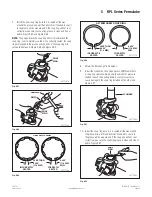
5 RPL Series Permalube
LARGE
DIAMETER
SMALL
DIAMETER
SHROUD
4001829a
Fig. 5.44
5. Align the slip yoke and spline shaft sections with the phasing
marks you made on these sections during disassembly.
Figure 5.45.
4001830c
PHASING MARKS
Fig. 5.45
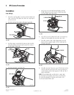
6. Install the spline shaft into the slip yoke until the splines fully
engage. Figure 5.45.
7. Snap the seal into the groove. Figure 5.46.
SEAL
4001831a
Fig. 5.46
8. Snap the shroud over the seal. Figure 5.47.
SHROUD
SEAL
4001832c
Fig. 5.47
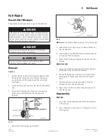
9. Push together the driveline sections. Figure 5.48.
4001834c
Fig. 5.48
Installation
Wing Bushings
WARNING
If you do not correctly install the universal joint and end yoke, the
bushings will not correctly seat in the yoke, which can cause the
capscrews that secure the universal joint to fatigue under normal
operating conditions. Serious personal injury and damage to
components can result.
The new design wing bushing has interference bosses on the
bushing. The bosses interfere with the end yoke if you attempt
to install the wing bushing incorrectly. You must install the
interference bosses away from the yoke. Figure 5.49.


