Copyright Meritor, Inc., 2021
MM-96147 / Revised 03-21
Page 40
(16579)
Printed in USA
5 RPL Series Permalube
Installation
Drive Flange
1. Ensure the snap ring grooves are clean and free of debris and
clean if necessary. If the groove has debris, the snap ring will
not seat correctly.
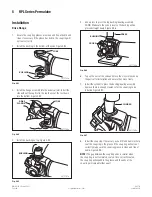
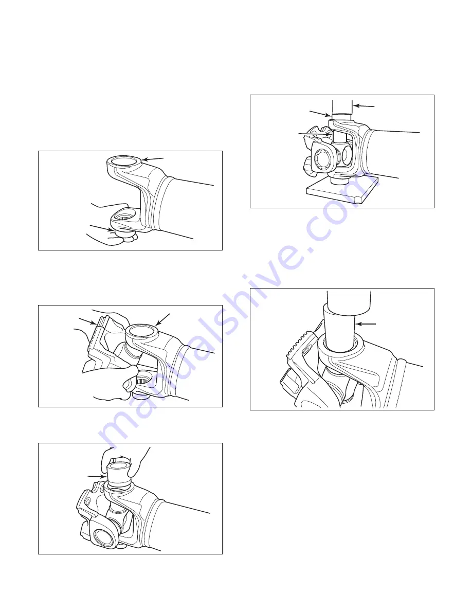
2. Install the bushing in the bottom of the yoke. Figure 5.93.
7011765a
YOKE
BUSHING
Fig. 5.93
3. Install the fl ange assembly into the universal joint. Install the
side without the cup fi rst in the top then seat the rest down
into the bottom. Figure 5.94.
4011766a
YOKE
DRIVE
FLANGE
Fig. 5.94
4. Install the bushing on top. Figure 5.95.
4011767a
BUSHING
Fig. 5.95
5. Use a press to press the top bushing/bearing assembly
DOWN. Make sure the yoke is level so the bushing will be
pressed straight down. Figure 5.96.
4011768a
PRESS
BUSHING
CROSS
Fig. 5.96
6. Tap on the ears of the yoke and move the cross to loosen up
the parts after installation and ensure they move freely.
7. Install the cylinder to press the bushing/bearing assembly
down so there is enough clearance for the snap ring to be
installed. Figure 5.97.
4011769a
CYLINDER
Fig. 5.97
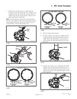
8. Install the snap ring. If necessary, use a drift and hammer help
seat the snap ring in the groove. If the snap ring will not seat
correctly, make sure the snap ring groove is clean and free of
debris. Figure 5.98.
NOTE:
The gap between the snap ring ends is smaller when
the snap ring is not completely seated. Once correctly seated,
the snap ring will expand in the groove and the ends of the
snap ring will spread further apart.


