Copyright Meritor, Inc., 2021
MM-96147 / Revised 03-21
Page 71
(16579)
Printed in USA
13 Troubleshooting
Driveline Runout
1. Use a jack to raise the rear axle. Support the vehicle with
safety stands.
2. Check each driveshaft for dents, bends, twists or other
damage.
3. Ensure that the driveshaft is straight within 0.030-inch
(0.76 mm) on the tube 3-4-inches (76-102 mm) from the
front and rear welds, and 0.030-inch (0.76 mm) at the center
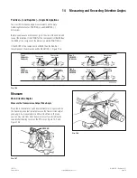
of the tube. Figure 13.5.
• If the driveshaft is not within these specifi cations:
Disconnect the driveshaft at the location it exceeds
0.030-inch (0.76 mm). Rotate the driveshaft 180° and
reattach. Check the runout again.
• If the driveshaft is still not within the specifi cation:
Remove the driveshaft and repair at a reputable driveline
repair facility.
4006681a
3-4"
(76-102 MM)
3-4"
(76-102 MM)
3-4"
(76-102 MM)
0.030"
(0.76 MM)
SLIP
YOKE*
0.030"
(0.76 MM)
Fig. 13.5
*Do not measure runout on the slip yoke. Measure only where
indicated.
Slip Yoke
NOTE:
For single one-piece driveline systems, check the slip yoke
for movement with the driveline installed and the vehicle on a
level surface with its wheels on the ground. For multiple driveline
systems, remove the slip yoke assembly from the vehicle to check
for movement.
1. Ensure that the vehicle is on a level surface with its wheels on
the ground. For single driveline systems, check the slip yoke
for movement with the driveline installed. For multiple driveline
systems, remove the slip yoke assembly from the vehicle and
check for movement.
2. Firmly mount a dial indicator with a magnetic base onto the
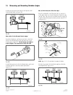
slip yoke barrel next to the dust seal. Figure 13.6. You don’t
want the dial indicator to move when you check the slip yoke
for looseness, or the measurement will not be correct.
NECK OF
SPLINE PLUG
The base of the
dial indicator must
be next to the dust
seal, as shown.
DUST
SEAL
SLIP YOKE
BARREL
3/4"
(19.05 MM)
MAXIMUM
4001871a
Fig. 13.6
3. Extend the dial indicator arm from the base, so that it contacts
the neck of the spline plug within 3/4-inch (19.05 mm) from
the dust seal. Figure 13.6.
4. With your hands near the center of the driveline, move the slip
yoke UP-AND-DOWN. Check the dial indicator measurement.
Movement between the spline plug and slip yoke must not
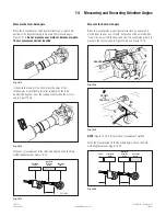
exceed 0.017-inch (0.432 mm). Figure 13.7 and Figure 13.8.
• If movement exceeds 0.017-inch (0.432 mm):
Components are worn or damaged. Replace as required.
4001793a
Fig. 13.7
Yoke-Style Driveline
4011840a
Fig. 13.8
Flange-Style Driveline


