Section 4
Assembly and Installation
Copyright 2002
Maintenance Manual MM-0230
Page 20
ArvinMeritor, Inc.
Issued 07-02
11. Use appropriate tools to screw the pinion cage
into the carrier while rotating the pinion to
seat the bearings.
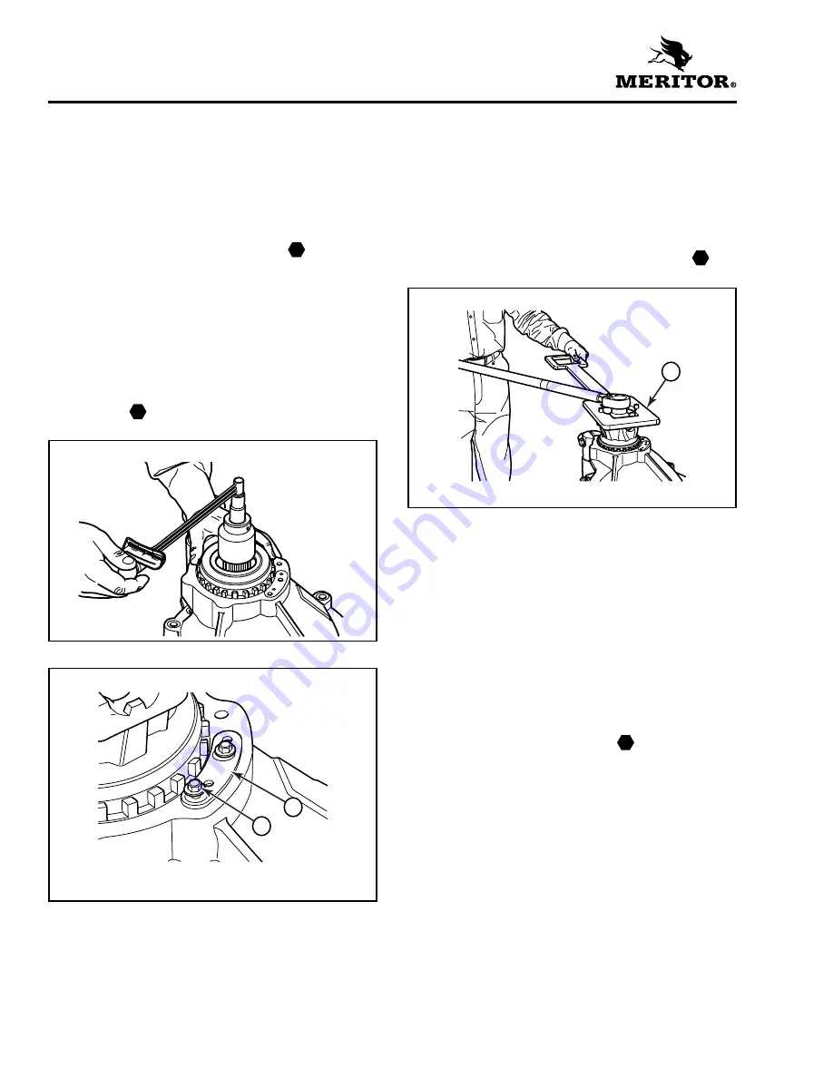
12. Tighten the pinion cage to adjust the drive
pinion bearing preload. Check the preload by
rotating the pinion by the yoke locknut with
a torque wrench. Figure 4.9. The correct
torque is 5-20 lb-in (5.8-23 N•m).
13. Position the pinion cage lock plate.
Figure 4.10.
O
If the lock plate does not match one of
the four possible positions: Tighten or
loosen the pinion cage while checking the
preload to keep it within specification.
14. Install the capscrews and tighten them to
10-13 lb-ft (14-18 N•m). Remove the yoke
locknut.
15. Install the yoke and locknut onto the drive
pinion shaft.
16. Fasten a yoke bar to the yoke to hold the drive
pinion in position when you tighten the
locknut. Figure 4.11. Refer to Section 9 to build
a yoke bar.
17. Tighten the locknut to 740-920 lb-ft
(1000-1245 N•m).
Remove the yoke bar.
Differential Case and Ring Gear into the
Carrier
1.
Install the bearing cup and adjusting ring into
the bore of the integral bearing cap side of
the carrier.
2.
Install the differential case and ring gear
assembly into the carrier.
3.
Install the bearing cup and adjusting ring into
the carrier on the bolted-on bearing cap side.
4.
Position the differential cap onto the carrier.
Install the capscrews and tighten them to
115-140 lb-ft (155-190 N•m).
5.
Adjust the differential bearings preload and
ring gear backlash. Check the tooth contact
patterns.
Figure 4.9
Figure 4.10
1
CAPSCREW
2
LOCK PLATE
T
T
2
1
Figure 4.11
1
YOKE BAR
T
1
T


