Maintenance Manual MM-0230
Copyright 2002
Issued 07-02
ArvinMeritor, Inc.
Page 21
Adjust Differential Bearing Preload
Use Method 1 or Method 2 below to adjust
differential bearing preload.
Specifications
Method 1
1.
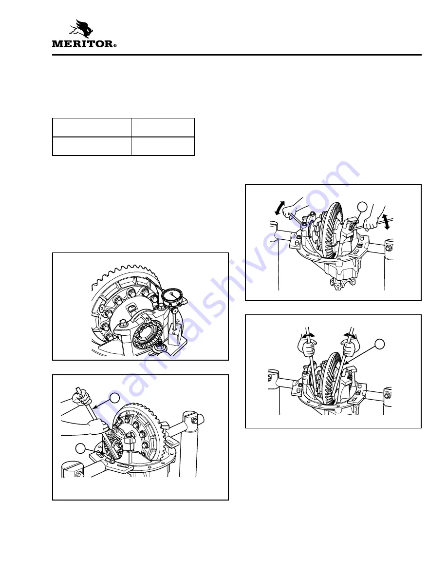
Attach a dial indicator onto the carrier
mounting flange so that the pointer is against
the ring gear’s back surface. Figure 4.12.
2.
Use a T-bar wrench to loosen the bearing
adjusting ring that is opposite the ring gear.
Figure 4.13. The dial indicator will show a
small amount of end play.
3.
Use one of the following procedures to move
the differential and ring gear to the LEFT and
RIGHT while you read the dial indicator.
A. Insert two pry bars between the bearing
adjusting rings and the ends of the
differential case. Figure 4.14. The pry bars
must not touch the differential bearings.
B. Insert two pry bars between the differential
case, or the ring gear and the carrier at
locations other than specified in Step A.
Figure 4.15. The pry bars must not touch
the differential bearings.
4.
Tighten the bearing adjusting ring until the dial
indicator reads ZERO end play. Move the
differential ring to the LEFT and RIGHT as
needed. If necessary, repeat Step A or B.
5.
Tighten each bearing adjusting ring one notch
from ZERO. Proceed to Check Ring Gear
Runout (Radial Movement) in this section.
Differential bearing
preload
15-35 lb-in
(1.7-3.5 N•m)
Expansion between
bearing caps
0.006-0.013-inch
(0.15-0.33 mm)
Figure 4.12
Figure 4.13
1
T-BAR WRENCH
2
ADJUSTING RING OPPOSITE RING GEAR
1
2
Figure 4.14
1
Pry bars must not touch bearings.
Figure 4.15
1
Pry bars must not touch bearings.
1
1


