background image


Section 2
Removal and Disassembly 


Copyright 2002

Maintenance Manual MM-0230

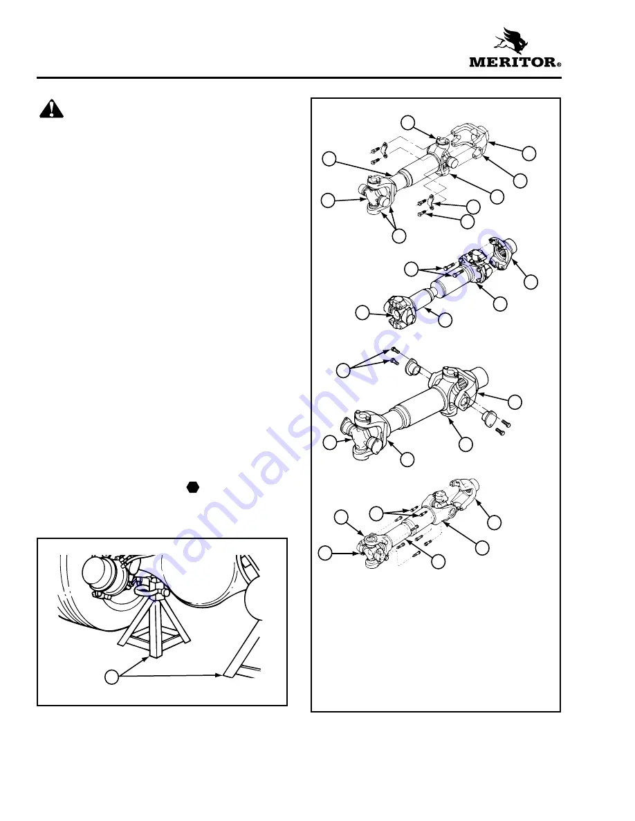
Page 2

ArvinMeritor, Inc.

Issued 07-02


Section 2

Removal and Disassembly

WARNING


To prevent serious eye injury, always wear safe 
eye protection when you perform vehicle 
maintenance or service.

Park the vehicle on a level surface. Block the 
wheels to prevent the vehicle from moving. 
Support the vehicle with safety stands. Do not 
work under a vehicle supported only by jacks. 
Jacks can slip and fall over. Serious personal 
injury and damage to components can result.

Use a brass or leather mallet for assembly and 
disassembly procedures. Do not hit steel parts 
with a steel hammer. Pieces of a part can break 
off and cause serious personal injury.


Removal


Axle Shafts from the Axle Assembly


1.

Park the vehicle on a level surface. Block the 
wheels to prevent the vehicle from moving. 

2.

Raise the rear end of the vehicle so that the 
rear wheels are off the ground. Support the 
vehicle with safety stands. 


Figure 2.1


.

3.

Place a drain pan under the rear axle.

4.

Remove the drain plug from the bottom of the 
axle housing. Drain the lubricant from the 
assembly. Install the drain plug and tighten it 
to 35-50 lb-ft (48-67 N•m). 

5.

Disconnect the driveline universal joint from 
the pinion input yoke on the carrier. 


Figure 2.2


.


Figure 2.1


1

SAFETY STANDS

T

1


Figure 2.2


1

FULL ROUND BEARING CUPS

2

END YOKE

3

YOKE SADDLE

4

WELD YOKE

5

BEARING STRAP

6

CAPSCREWS

7

EASY-SERVICE BEARING 
CUPS

8

U-JOINT CROSS

9

SLIP YOKE

10 CAPSCREWS
11 END YOKE
12 WELD YOKE

13 SLIP YOKE
14 U-JOINT CROSS
15 CAPSCREWS
16 END YOKE
17 WELD YOKE
18 SLIP YOKE
19 U-JOINT CROSS
20 CAPSCREWS
21 END YOKE
22 SLIP YOKE
23 TUBING
24 U-JOINT CROSS
25 WELD YOKE

12

13

11

14

10

7

8

6

4

5

1

2

3

9

16

15

17

18

19

EASY SERVICE

TM

WING SERIES

PERMALUBE

TM

FULL-ROUND

“RPL” SERIES,
PERMALUBE

TM

23

24

22

20

21

25

Summary of Contents for MS-113

Page 1: ...Rear Axle Single Reduction Carrier Model MS 113 Maintenance Manual MM 0230 Issued 07 02 2 50 ...

Page 2: ... Information by Phone Call ArvinMeritor s Customer Service Center at 800 535 5560 to order the following publications O Approved Rear Drive Axle Lubricants Technical Bulletin TP 9539 O Failure Analysis for Drive Axle Components Manual TP 9955 O Lubrication Maintenance Manual 1 O Drive Axle Housings Maintenance Manual 8 O Drivetrain PlusTM by ArvinMeritor Technical Electronic Library on CD Features...

Page 3: ... Drive Axle Housing 12 Removing Fasteners Secured with Adhesive 13 Install Fasteners New Fasteners with Pre Applied Adhesive Original or Used Fasteners Using Meritor Liquid Adhesive 2297 C 7049 or Loctite 680 Adhesive or Equivalent Applying Meritor Specification 2297 T 4180 Adhesive in the Bearing Bores Differential Applying Three Bond 1216 or Equivalent Silicone Gasket Material 14 Gear Sets 15 Ex...

Page 4: ...31 Contaminated Lubricant Found During Preventive Maintenance 32 Section 6 Torque Specifications 33 Section 7 Lubrication 34 Section 8 Towing Instructions Before Towing or Drive Away 36 After Towing or Drive Away 37 Section 9 Special Tools Carrier Repair Stand Specifications 38 How to Make a Yoke Bar 39 ...

Page 5: ...k Plate 17 Thrust Washer 29 Carrier to Housing Capscrew M12 x 1 75 x 60 6 Pinion Cage 18 Differential Pinion 30 Carrier to Housing Capscrew M12 x 1 75 x 30 7 O Ring 19 Adjusting Ring 31 Breather 8 Outer Bearing Cup 20 Bearing Cup 32 Axle Housing 9 Outer Bearing Cone 21 Bearing Cone 33 Fill Plug 10 Drive Pinion 22 Ring Gear 34 Drain Plug 11 Shim 23 Differential Case Ring Gear Side 35 Axle Shaft 12 ...

Page 6: ...ing Figure 1 1 The carrier has a hypoid drive pinion and ring gear set Bevel gears are used in the differential assembly All bearings in the carrier are tapered roller bearings When the carrier operates there is normal differential action between the wheels all the time Figure 1 1 1 ADJUSTING RING 2 CARRIER 3 RING GEAR AND DRIVE PINION 4 TAPERED ROLLER BEARING 5 TAPERED ROLLER BEARING 6 HOUSING 7 ...

Page 7: ...els to prevent the vehicle from moving 2 Raise the rear end of the vehicle so that the rear wheels are off the ground Support the vehicle with safety stands Figure 2 1 3 Place a drain pan under the rear axle 4 Remove the drain plug from the bottom of the axle housing Drain the lubricant from the assembly Install the drain plug and tighten it to 35 50 lb ft 48 67 N m 5 Disconnect the driveline univ...

Page 8: ...crews in the TOP of the carrier that secure the carrier to the axle housing 5 Use a hydraulic roller jack and pry bar with a round end to remove the carrier from the axle housing Take care when you use the pry bar so that you don t damage the carrier or housing flange WARNING To avoid serious personal injury and damage to components take care when using lifting devices during service and maintenan...

Page 9: ...erential bearing cap capscrews and the cap Figure 2 8 3 Remove the differential adjusting ring and bearing cup from bolted on bearing cap side Figure 2 9 4 Remove the differential assembly from the carrier and place it onto a workbench 5 Remove the differential adjusting ring and bearing cup from integral bearing cap side Drive Pinion from the Carrier 1 Fasten a yoke bar onto the yoke to hold the ...

Page 10: ...from the carrier 6 Remove the pinion cage and the drive pinion from the carrier 7 Remove the drive pinion inner bearing cup from the carrier Disassembly WARNING Observe all warnings and cautions provided by the press manufacturer to avoid damage to components and serious personal injury Differential Case and Ring Gear 1 Remove the capscrews from the differential case Figure 2 13 Figure 2 10 1 YOKE...

Page 11: ...ntial pinion shaft differential pinions and thrust washers Figure 2 16 4 Remove the side gear and thrust washer Figure 2 17 Use a brass hammer to remove the ring gear from the differential case Figure 2 18 Figure 2 14 Figure 2 15 1 THRUST WASHER 2 SIDE GEAR 1 2 Figure 2 16 1 DIFFERENTIAL PINION 2 THRUST WASHER 3 DIFFERENTIAL PINION SHAFT Figure 2 17 1 SIDE GEAR 2 THRUST WASHER Figure 2 18 1 RING G...

Page 12: ...n 1 Remove and discard the pinion cage O ring Figure 2 20 2 Remove the outer bearing cup and seal from the pinion cage Discard the seal 3 Use a bearing puller or a press to remove the inner and outer bearing cones from the drive pinion 4 Remove the shim from the drive pinion Figure 2 19 1 DIFFERENTIAL CASE Figure 2 20 1 PINION CAGE 2 O RING 3 OUTER BEARING CUP 4 OUTER BEARING CONE 5 DRIVE PINION 6...

Page 13: ...ound or polished parts Damage to parts will result 3 Do not clean ground or polished parts with water or steam Do not immerse ground or polished parts in a hot solution tank or use strong alkaline solutions for cleaning or the smooth sealing surface may be damaged Clean Rough Parts 1 Clean rough parts with the same method as cleaning ground and polished parts 2 Rough parts can be cleaned in hot so...

Page 14: ...us at the large diameter end of the rollers is worn to a sharp edge Figure 3 1 O There is a visible roller groove in the cup or cone inner race surfaces The groove can be seen at the small or large diameter end of both parts Figure 3 2 O There are deep cracks or breaks in the cup cone inner race or roller surfaces Figure 3 2 O There are bright wear marks on the outer surface of the roller cage Fig...

Page 15: ...ntial pinion shaft O Teeth and splines of both differential side gears O Teeth and bore of all differential pinions 4 Inspect axle shafts for wear and cracks at the flange shaft and splines Replace the axle shafts if required Repair or Replace Parts NOTE Threads must be without damage and clean so that accurate adjustments and correct torque values can be applied to fasteners and parts 1 Replace a...

Page 16: ... The high temperature caused by the open flame from the cutting torch can ignite the oil in the axle housing and can cause serious personal injury 1 Remove the oil drain plug from the bottom of the axle housing and drain the lubricant from the assembly CAUTION Remove the differential carrier from the axle housing before you weld onto an axle Do not weld onto an axle with the differential carrier i...

Page 17: ...C before you begin welding 8 Use suitable weld wire electrodes when you weld Suitable weld wire electrodes include either BS EN 499 E 42 2 B 32 H5 or BS EN 440 G 42 2 M GSi American Welding Society equivalents E7018 and ER70S3 respectively 9 For complete welding instruction refer to Maintenance Manual 8 To obtain this publication refer to the Service Notes page on the front inside cover of this ma...

Page 18: ...sive 2297 C 7049 or Loctite 680 Adhesive or Equivalent WARNING Take care when you use Loctite to avoid serious personal injury Follow the manufacturer s instructions to prevent irritation to the eyes and skin 1 Use a wire brush to clean the oil dirt and old adhesive from all threads and threaded holes 2 Apply four or five drops of Meritor liquid adhesive Loctite 680 adhesive or equivalent inside e...

Page 19: ...he gear set as required Refer to Section 4 Applying Three Bond 1216 or Equivalent Silicone Gasket Material WARNING When you apply some silicone gasket materials small amounts of acid vapor are present To prevent serious personal injury ensure that the work area is well ventilated If the silicone gasket material gets into your eyes flush them with water for 15 minutes Have your eyes checked by a ph...

Page 20: ...umbers to verify that the gear set you will install has matched parts Figure 3 15 Examples Gear Set Gear Set Tooth Combination Number Gear Set Match Number NOTE Meritor s drive pinions and ring gears are only available as matched sets Each gear in a set has an alpha numeric match number Figure 3 14 1 0 125 3 MM DIAMETER SILICONE GASKET BEAD 1 Figure 3 15 ALTERNATE LOCATIONS 1 PART NUMBER TOOTH COM...

Page 21: ...on Number NOTE Don t use the pinion cone variation number when you check for a matched gear set Use this number when you adjust the pinion depth in the carrier Refer to Section 4 Pinion Cone PC Variation Number Drive Pinion Location Ring Gear Location PC 3 2 0 01 mm PC 5 1 0 02 mm At the end of the pinon gear head On the outer diameter ...

Page 22: ...because of the tight fit 2 Heat the ring gear A maximum temperature of 340 F 170 C can be applied at the gear web The temperature at the gear teeth must not exceed 250 F 120 C Wear safe clothing and gloves while working with the hot ring gear 3 Position the differential case on a workbench with the bearing cone on top 4 Place the ring gear over the differential case immediately after the gear is h...

Page 23: ...l pinion shaft in the differential case on top of the side gear The holes in the differential pinion shaft must align with the capscrew holes in the differential case Figure 4 4 12 Install the side gear and thrust washer over the differential pinions Figure 4 5 13 Position the case half over the side gear Figure 4 6 Figure 4 2 1 SIDE GEAR 2 THRUST WASHER Figure 4 3 1 DIFFERENTIAL PINION 2 THRUST W...

Page 24: ... the differential case and inspect parts for wear or damage Repair or replace parts as necessary Reassemble the differential case and repeat Steps 2 through 4 Installation Drive Pinion into the Carrier 1 Install the drive pinion inner bearing cup into the carrier 2 Apply axle lubricant onto the carrier pinion cage bore and inner bearing cup 3 Apply axle lubricant onto the pinion inner and outer co...

Page 25: ... the yoke locknut 15 Install the yoke and locknut onto the drive pinion shaft 16 Fasten a yoke bar to the yoke to hold the drive pinion in position when you tighten the locknut Figure 4 11 Refer to Section 9 to build a yoke bar 17 Tighten the locknut to 740 920 lb ft 1000 1245 N m Remove the yoke bar Differential Case and Ring Gear into the Carrier 1 Install the bearing cup and adjusting ring into...

Page 26: ...ing adjusting rings and the ends of the differential case Figure 4 14 The pry bars must not touch the differential bearings B Insert two pry bars between the differential case or the ring gear and the carrier at locations other than specified in Step A Figure 4 15 The pry bars must not touch the differential bearings 4 Tighten the bearing adjusting ring until the dial indicator reads ZERO end play...

Page 27: ...t the bearing caps have expanded Refer to the following example O If the measurement is 0 006 0 013 inch 0 15 0 33 mm Proceed to Check Ring Gear Runout Radial Movement in this section O If the measurement is not within the specification above Repeat Steps 3 and 4 as necessary Sample Differential Bearing Preload Calculation Check Ring Gear Runout Radial Movement 1 Attach a dial indicator onto the c...

Page 28: ... the mounting flange of the carrier Figure 4 19 2 Adjust the dial indicator so that the plunger or pointer is against the tooth surface 3 Adjust the dial indicator to ZERO Hold the drive pinion in position 4 After reading the dial indicator rotate the differential and ring gear a small amount in both directions against the drive pinion teeth O If the backlash reading is within specification Check ...

Page 29: ...tely 12 gear teeth of the ring gear Rotate the ring gear so that the 12 gear teeth are next to the drive pinion Figure 4 24 3 Rotate the ring gear forward and backward so that the 12 gear teeth go past the drive pinion six times to get the contact patterns Repeat if needed to get a clearer pattern 4 Look at the contact patterns on the ring gear teeth Compare the patterns to Figures 4 25 4 26 and 4...

Page 30: ...between the top and bottom of the gear teeth Use the following procedure A Disassemble the yoke pinion cage and the drive pinion Refer to Section 2 B Remove the inner bearing cone from the drive pinion Refer to Section 2 C Change the bearing shim O To correct a high contact pattern Figure 4 26 Replace the bearing shim with a thicker shim O To correct a low contact pattern Figure 4 27 Replace the b...

Page 31: ...ct patterns toward the heel of the ring gear teeth Figure 4 30 C Repeat Steps 2 4 and 6 until the contact patterns are at the correct location in the length of the gear teeth 7 Install the cotter pins into the adjusting rings so that the large end is between the adjusting ring lugs Bend the tabs out flat against the outboard side of the leg caps in two places Figure 4 31 Figure 4 29 1 Move pattern...

Page 32: ...and the carrier mounting surfaces Use a cleaning solvent and rags to remove dirt Blow dry the cleaned areas with air Refer to Section 3 2 Inspect the axle housing for damage Repair or replace the axle housing Refer to Section 3 3 Apply Meritor specification 2297 T 4180 liquid adhesive or equivalent into the threaded holes in the axle housing To obtain this adhesive refer to the Service Notes page ...

Page 33: ...155 N m 5 Connect the driveline universal joint to the pinion input yoke on the carrier 6 Remove the safety stands Lower the vehicle Remove the blocks from the wheels Fill the Axle with Lubricant 1 Park the vehicle on a level surface 2 Remove the fill plug from the axle housing 3 Fill the axle housing with the correct lubricant until the lubricant level is to the bottom of the fill plug hole Refer...

Page 34: ...rrier from the axle housing Repair the carrier or install a remanufactured carrier Refer to Section 2 Drain and inspect the lubricant Refer to MM 1 Remove the carrier from the axle housing Refer to Section 2 Visually inspect the ring gear and pinion for damage Refer to TP 9955 Failure Analysis for Drive Axle Components Repair the carrier or install a remanufactured carrier Refer to Section 4 Repai...

Page 35: ...he axle housing Repair the carrier or install a remanufactured carrier Refer to Section 2 Drain and inspect the lubricant Refer to MM 1 Check the drive pinion end play Refer to Section 4 Any end play looseness indicates possible bearing damage Remove the carrier from the axle housing Refer to Section 2 Visually inspect the ring gear and pinion for damage Refer to TP 9955 Failure Analysis for Drive...

Page 36: ...e axle housing Remove the carrier from the axle housing Repair the carrier or install a remanufactured carrier Refer to Section 2 Inspect the axle housing welds for cracks or leaks If you find weld cracks contact Meritor for repair welding procedures Fill the carrier with the correct amount of the specified lubricant Refer to Section 6 Clean the seal area Test drive the vehicle to confirm that the...

Page 37: ...fer to Section 2 Drain and inspect the lubricant Refer to MM 1 Replace the pinion seal with a unitized seal Replace the pinion cage O ring with a new O ring Joint leaking No Yes Test drive the vehicle to confirm that the leak is repaired Return the vehicle to service Send out a lubrication sample for analysis Advise the owner to return for the results Inspect the axle housing welds for cracks or l...

Page 38: ... 008 inch 0 200 mm maximum Backlash Setting Range for Old Gear Sets 0 008 0 018 inch 0 20 0 46 mm Backlash Setting for New Gear Sets 0 005 0 015 inch 0 13 0 38 mm Fastener Size Torque Value lb ft N m Yoke Locknut M32 x 1 5 740 920 1000 1245 Adjusting Ring Lock Plate Capscrews M6 x 1 0 Class 10 9 10 13 14 18 Differential Case Capscrews M12 x 1 75 Class 10 9 105 115 140 155 Differential Cap Capscrew...

Page 39: ... Pints Liters 14 6 8 Vocation or Vehicle Operation Motorhome Recreational Vehicle Commercial Van Beverage Truck Stake Truck Wrecker City Delivery School Bus Fire Truck Municipal Truck Utility Truck Initial Oil Change No longer required as of January 1 1993 Check Oil Level Every 25 000 miles 40 000 km or the fleet maintenance interval whichever comes first Every 10 000 miles 16 000 km once a month ...

Page 40: ...th EP Additives GL 5 85W 140 O 76A MIL PRF 2105E and SAE J2360 Above 10 F 12 C 80W 140 O 76B Above 15 F 26 C 80W 90 O 76D Above 15 F 26 C 75W 90 O 76E Above 40 F 40 C 75W O 76J From 40 F 40 C to 35 F 2 C 75W 140 O 76L Above 40 F 40 C Extended Drain Lubricants Petroleum with Extended Drain Additives GL 5 80W 90 MIL PRF 2105E and SAE J2360 Above 15 F 26 C Semi Synthetic 80W 90 Above 15 F 26 C Full S...

Page 41: ...e axle shaft from the axle assembly Figure 8 1 5 Install a cover over the open end of each hub where an axle shaft was removed This will prevent dirt from entering the bearing cavity and loss of lubricant NOTE If an air supply will be used for the brake system of the transported vehicle continue with Steps 6 and 7 otherwise continue with Step 8 6 Connect an auxiliary air supply to the brake system...

Page 42: ...started Refer to the manufacturer s instructions 3 Disconnect the auxiliary air supply if used from the brake system of the vehicle that was transported Connect the vehicle s air supply to the brake system 4 Remove the covers from the hubs NOTE Continue with Steps 5 6 to install all axle shafts 5 Install the axle shaft into the axle housing and carrier in the same location it was removed from The ...

Page 43: ...meter x 9 228 6 mm long with one end slotted to fit plate 4 Weld all around after pressing plug into pipe 5 Weld 6 Shape and size of holes to fit carrier 7 23 1 2 596 9 mm center to center of pipe 8 Chamfer end of pipe for welding 9 4 101 6 mm diameter pipe 10 Plug 4 101 6 mm diameter x 7 177 8 mm long with one end turned 3 76 2 mm long to fit pipe Drill 2 50 8 mm hole and mill 3 16 4 76 mm wide s...

Page 44: ... Welding equipment can burn you and cause serious personal injury Follow the operating instructions and safety procedures recommended by the welding equipment manufacturer 3 To make the box section cut and weld 1 0 inch x 2 0 inch 25 4 mm x 50 8 mm mild steel square stock according to dimensions C and D Figure 9 2 4 Cut a 4 0 foot x 1 25 inch 1 21 m x 31 75 mm piece of mild steel round stock to ma...

Page 45: ... the publication was approved for printing and is subject to change without notice or liability Meritor Heavy Vehicle Systems LLC reserves the right to revise the information presented or to discontinue the production of parts described at any time Copyright 2002 Maintenance Manual MM 0230 ArvinMeritor Inc Issued 07 02 All Rights Reserved Printed in the USA 16579 24240 ...

Reviews: