TP-9579B
Revised 12-09
16579
Page 2
© Copyright Meritor Automotive, Inc., 2009
Printed in the USA
CAUTION
On single and tandem rear axles equipped with a
DCDL, when removing the curb-side (right) axle
shaft, the DCDL shift collar splines must be
engaged with the differential case splines. The
collar splines must be completely engaged with
the differential case splines. This must be done to
prevent the shift collar from dropping out of
position when removing the axle shaft. Cage
(engage) the shift collar with the differential case
before removing the axle shaft or damage to
components can result.
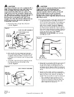
a. Disconnect the air hose from the shift
cylinder.
Figure 1
.
b. Remove the manual engaging capscrew
from the storage hole. The storage hole of
threaded shift assemblies is located in the
shift tower of the carrier, next to the cylinder.
Figure 1
.
c. Install the manual engaging capscrew into
the threaded hole in the center of the
cylinder.
Figure 2
.
CAUTION
When you turn the capscrew in Step d and you feel
a high resistance, STOP TURNING THE
CAPSCREW. A high resistance against the
capscrew indicates that the splines of the shift
collar and differential case are not aligned.
Damage to the threads of the cylinder and
capscrew will result. To align the splines, continue
with Steps e and f.
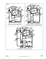
d. Turn the capscrew to the right until the head
is approximately 0.25 to 0.50-inch (6.4 to
12.7 mm) from the cylinder. The capscrew is
now in the service position and the DCDL
shift collar is locked (engaged).
Figure 3
.
When turning the capscrew you will feel a
small amount of resistance. This is normal.
If you feel a high resistance before achieving
the 0.25- to 0.50-inch distance between the
capscrew head and cylinder,
STOP
TURNING THE CAPSCREW
and continue
with Steps e and f.
e. Raise the tire and wheel (DCDL axle side) off
of the floor (leave the opposite tire and
wheel on the floor) and support the axle
with jack stands. Slowly rotate the wheel of
the DCDL axle shaft that is to be removed by
hand.
f. Verify that the clutch collar is engaged by
attempting to rotate the elevated wheel. If it
does not rotate, the collar is successfully
caged. The axle shaft can now be removed.
•
If you still feel a high resistance:
Stop
turning the capscrew, disassemble and
inspect components for damage and
wear. Replace as necessary.
Figure 1
Figure 2
STORAGE
HOLE
CYLINDER
SHIFT
TOWER
MANUAL ENGAGING
CAPSCREW
AIR HOSE
THREADED
SHIFT ASSEMBLY
THREADED
SHIFT ASSEMBLY
MANUAL
ENGAGING
CAPSCREW
Figure 3
CYLINDER
0.25" to 0.50"
(6.4 to 12.7 mm)


