background image

TP-9579C
Revised 12-09

16579/22882

Page 2

© Copyright Meritor Automotive, Inc., 2009

Printed in the USA

CAUTION

On single and tandem rear axles equipped with a 
DCDL, when removing the curb-side (right) axle 
shaft, the DCDL shift collar splines must be 
engaged with the differential case splines. The 
collar splines must be completely engaged with 
the differential case splines. This must be done to 
prevent the shift collar from dropping out of 
position when removing the axle shaft. Cage 
(engage) the shift collar with the differential case 
before removing the axle shaft or damage to 
components can result.

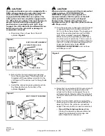
a. Disconnect the air hose from the shift 

cylinder. 

Figure 1

.  

b. Remove the manual engaging capscrew 

from the storage hole. The storage hole of 
threaded shift assemblies is located in the 
shift tower of the carrier, next to the cylinder. 

Figure 1

c. Install the manual engaging capscrew into 

the threaded hole in the center of the 
cylinder. 

Figure 2

.  

CAUTION

When you turn the capscrew in Step d and you feel 
a high resistance, STOP TURNING THE 
CAPSCREW. A high resistance against the 
capscrew indicates that the splines of the shift 
collar and differential case are not aligned. 
Damage to the threads of the cylinder and 
capscrew will result. To align the splines, continue 
with Steps e and f. 

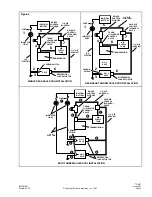
d. Turn the capscrew to the right until the head 

is approximately 0.25 to 0.50-inch (6.4 to 
12.7 mm) from the cylinder. The capscrew is 
now in the service position and the DCDL 
shift collar is locked (engaged). 

Figure 3

When turning the capscrew you will feel a 
small amount of resistance. This is normal. 
If you feel a high resistance before achieving 
the 0.25- to 0.50-inch distance between the 
capscrew head and cylinder, 

STOP 

TURNING THE CAPSCREW

 and continue 

with Steps e and f.  

e. Raise the tire and wheel (DCDL axle side) off 

of the floor (leave the opposite tire and 
wheel on the floor) and support the axle 
with jack stands. Slowly rotate the wheel of 
the DCDL axle shaft that is to be removed by 
hand. 

f. Verify that the clutch collar is engaged by 

attempting to rotate the elevated wheel. If it 
does not rotate, the collar is successfully 
caged. The axle shaft can now be removed.

If you still feel a high resistance:

 Stop 

turning the capscrew, disassemble and 
inspect components for damage and 
wear. Replace as necessary.

Figure 1

Figure 2

TOP SIDE STORAGE HOLE

AIR HOSE

CYLINDER
COVER

CENTER HOLE

BOTTOM SIDE
STORAGE HOLE

PLUG AND
GASKET

MANUAL
ENGAGING
CAPSCREW

BOLT ON SHIFT ASSEMBLY

BOLT ON SHIFT ASSEMBLY

MANUAL 
ENGAGING
CAPSCREW

Figure 3

0.25" to 0.50"
(6.4 to 12.7 mm)

Summary of Contents for TP-9579

Page 1: ...9579A Axle Preparation Instructions for Vehicle Towing or New Vehicle Drive Away Piggybacking Single axle without DCDL Tandem axle without DCDL with IAD TP 9579B Axle Preparation Instructions for Vehi...

Page 2: ......

Page 3: ...ase gearing and axle shafts together This feature maximizes traction to both wheels The lock position will also protect against spinout damage to the differential The DCDL should not be actuated when...

Page 4: ...n the DCDL is fully locked the vehicle will have an understeer condition when making turns Proceed cautiously over poor road or highway conditions NEVER exceed 25 mph and use good driving judgment Unl...

Page 5: ...trolled 2 The IAD switch should be in the UNLOCK position for normal operating conditions where there is good traction 3 Lock the IAD when approaching or anticipating icy or poor driving conditions to...

Page 6: ...All Rights Reserved 16579 Driver Instructions Locking the IAD When encountering poor road or highway conditions where a decrease in traction is anticipated follow the recommended procedures 1 Let up...

Page 7: ...Drivers may lock BOTH the IAD and the DCDL for maximum traction under icy snowy or poor road conditions However when using both of these traction enhancement devices or the DCDL alone vehicle speed m...

Page 8: ...low speed range to allow the differential to lock 2 Let up momentarily on the accelerator to relieve torque on the gearing allowing the differential to lock 3 When the differential lock is activated...

Page 9: ...ntial lock is deactivated the indicator light will be off or the audible signal will stop 4 Resume driving at normal speed using good driving judgment Unlocking the IAD When poor road or highway condi...

Page 10: ...fect at the time the publication was approved for printing and is subject to change without notice or liability Meritor Heavy Vehicle Systems LLC reserves the right to revise the information presented...

Page 11: ...lowing procedure Before Towing or Drive Away Piggybacking WARNING To prevent serious eye injury always wear safe eye protection when you perform vehicle maintenance or service WARNING Engage the parki...

Page 12: ...ansporting or repair is completed Example Match mark a mating axle shaft and hub 8 Remove the tapered dowels gasket if used and the axle shaft from the axle assembly Figure 1 9 Install a cover over th...

Page 13: ...e hubs NOTE Continue with Steps 5 7 to install all axle shafts 5 Install the gasket if used and axle shaft into the axle housing and carrier in the same location it was removed from The gasket and fla...

Page 14: ...e the publication was approved for printing and is subject to change without notice or liability Meritor Heavy Vehicle Systems LLC reserves the right to revise the information presented or discontinue...

Page 15: ...rive Away Piggybacking WARNING To prevent serious eye injury always wear safe eye protection when you perform vehicle maintenance or service WARNING Engage the parking brake to prevent the vehicle fro...

Page 16: ...are not aligned Damage to the threads of the cylinder and capscrew will result To align the splines continue with Steps e and f d Turn the capscrew to the right until the head is approximately 0 25 to...

Page 17: ...ch 38 1 mm diameter brass hammer can be used as a drift a Hold a 1 5 inch 38 1 mm diameter brass drift against the center of the axle shaft flange INSIDE THE ROUND DRIVING LUGS Figure 5 b Hit the end...

Page 18: ...service WARNING Engage the parking brake to prevent the vehicle from moving before you begin maintenance or service procedures that require you to be under the vehicle Serious personal injury can res...

Page 19: ...EARINGS SHIFT ASSEMBLY SCREW IN STYLE THREADED SHIFT COLLAR AXLE SHAFT SPLINES TAPERED ROLLER BEARING DIFFERENTIAL CASE BEVEL DIFFERENTIAL GEARS HOUSING TAPERED ROLLER BEARING STRAIGHT ROLLER BEARING...

Page 20: ...engaging capscrew from the shift assembly 9 Install the manual engaging capscrew into the storage hole The storage hole of threaded shift assemblies is located in the shift tower of the carrier next...

Page 21: ...Drive Away Piggybacking WARNING To prevent serious eye injury always wear safe eye protection when you perform vehicle maintenance or service WARNING Engage the parking brake to prevent the vehicle fr...

Page 22: ...age to the threads of the cylinder and capscrew will result To align the splines continue with Steps e and f d Turn the capscrew to the right until the head is approximately 0 25 to 0 50 inch 6 4 to 1...

Page 23: ...inch 38 1 mm diameter brass hammer can be used as a drift a Hold a 1 5 inch 38 1 mm diameter brass drift against the center of the axle shaft flange INSIDE THE ROUND DRIVING LUGS Figure 5 b Hit the e...

Page 24: ...or service WARNING Engage the parking brake to prevent the vehicle from moving before you begin maintenance or service procedures that require you to be under the vehicle Serious personal injury can...

Page 25: ...AFT DOUBLE ROW OF SPLINES SHIFT COLLAR AND DIFF CASE SPLINES ENGAGED LOCKED SIDE GEAR DIFFERENTIAL CASE SINGLE AXLE OR REAR AXLE OFTANDEM Shown with bolted on shift assembly Shown in the locked engage...

Page 26: ...Install the manual engaging capscrew into the storage hole The storage hole of bolted on shift assemblies is located in the top side of the shift cylinder cover Tighten to 15 25 Ib ft 20 35 N m Figur...

Page 27: ...ssembly are locked together When the carrier operates with the differential lock ENGAGED there is no differential action between the wheels of the axle When the carrier is operated with the differenti...

Page 28: ...plunger must be the type that is held in by air pressure and automatically releases when the air pressure is discontinued Use a Midland valve KNZ 0031 KNZ 0033 or equivalent 5 Connect an air line from...

Page 29: ...4 5 7 8 6 REAR REAR TANDEM AXLE DCDL INSTALLATION FUSE INDICATOR LIGHT 12 V ELECTRIC DRIVER CONTROL PLUNGER AIR SUPPLY TANK TRANSMISSION 1 4 AIR SERVICE TRANS LOW RANGE CONTROL VALVE 1 4 AIR CONTROL D...

Page 30: ...e the publication was approved for printing and is subject to change without notice or liability Meritor Heavy Vehicle Systems LLC reserves the right to revise the information presented or to disconti...

Page 31: ......

Page 32: ...ffect at the time the publication was approved for printing and is subject to change without notice or liability Meritor Heavy Vehicle Systems LLC reserves the right to revise the information presente...

Reviews: