background image

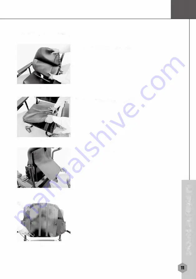
Seat Width Adjustment

(1) Remove the cushion ass'y

Fig D1 

(2) Remove seat cushion ass'y

Fig  D2 

(3) Lift the back cover

.. 

Fig  D3 

=. 

... 

-

-

.. 

51 

Fig  D4 

-

.. 

... 

Summary of Contents for Vision Ultra HD P331

Page 1: ...merits www me rltsusa com P331 Seating System Vision Ultra HD...

Page 2: ...epthAdjustment 15 SeatHeightAdjustment 16 BackrestAngleAdjustment 18 Safety Switch 20 Footplate 21 Elevating Leg Rests 22 High PivotPower Elevating Leg Rests 24 PowerArticulating Footplate 26 Operatin...

Page 3: ...may wish to customize the settings to fit your own personal preferences A wide range of customization options can be adjusted such as tilting reclining and elevating safety controls better maneuverabi...

Page 4: ...tically re engaged The solenoid electromechanical brakes allow the user stop by letting go of the joystick The intended function of the R Series Positioning System for Powered Wheelchair is to aid in...

Page 5: ...unintended directions It can also permanently damage the power product control system The intensity of the EM energy can be measured in volts per meter V m Each power product can resist EMI up to a ce...

Page 6: ...ll acquaint you with the many features of your rehab seat and how they work Upon receipt of your rehab seat inspect it for any damage Your rehab seat consists of the following components P331 R Series...

Page 7: ...I...

Page 8: ...tem Specification Model Tilt Tilt Recline optional Seat Width 18 24 18 24 Dimension Depth 16 20 16 20 Height 22 22 Seat Tilt Power Power Function Recline Manual 90 110 Power Elevate N A N A Actuator D...

Page 9: ...sticks have an integral controller Armrests Where arms can rest during time spent on powerbase wheelchair Footrest Where feet rest during time spent on the powerbase wheelchair Rehab Seat adjustment H...

Page 10: ...g B2 3 1 Angle adjustment Loosen the screw with the Allen key then move the armrest pivot ass y up and down to desired position then tighten the screw Fig B1 2 Height adjustment a Loosen the lever to...

Page 11: ...sired position then reinstall and tighten the screw Fig B 2 4 d Loosen the screw with the Allen key then move the armrest pivot up and down to desired position then tighten the screw Fig B1 1 Fig B1 2...

Page 12: ...C2 Adjustment of the joystick position Swing back controller bracket Fig C1 1 Use Allen key to loosen both screws then move controller bracket forward and backward to desired position tretighten scre...

Page 13: ...Seat Width Adjustment 1 Remove the cushion ass y Fig D1 2 Remove seat cushion ass y Fig D2 3 Lift the back cover Fig D3 M a a n a 51 Fig D4 a...

Page 14: ...board 8 Use anAllenkey to remove the screws of the adjust side tubes onthe seat base ass y 4 pieces at right and 4 at left then move the side adjustable tubes left and right to the appropriate positi...

Page 15: ...please place the same positions on both sides of holes It cannot be offset to one side Attention When assembling the back board back please place the same positions on both sides of holes It cannot b...

Page 16: ...everse the above processes Fig D10 Fig D1 then we can assemble the parts back Attention the shift distance of the left adjust side tube and the right adjust side tube have to the same It cannot be off...

Page 17: ...d then remove the seat board Fig D6 4 Use an Allen key to remove the screws and nuts of the backrest left and right and then move front rear directions to the appropriate position then put the screws...

Page 18: ...1 owner s Manual Seat Height Adjustment Fig E1 Fig E2 Fig E4 1 Remove the seat frame cover 2 Unplug the controller connectors 3 Unplug the main cable connectors 6 Use an Allen key to remove the seat a...

Page 19: ...time to remove the seat from the power chair and place it on the ground Fig ES 10 Remove the frame cover Fig ES 11 Remove the pin as shown in the photo and adjust the seat support frame ass y to the...

Page 20: ...ackrest Angle Adjustment 1 Remove the cushion Fig P1 Fig P1 2 Remove the seat cushion Fig P2 Fig P2 3 Remove the back cover Fig P3 Fig P3 4 Use the tool to loosen 10 screws Fig P4 Fig P4 5 Use the too...

Page 21: ...Angle Adjustment Fig P6 Fig P7 6 Hold the backrest use the tool to loosen screw and nut at the another side Fig P6 7 Please refer the photo to adjust the backrest angle in your desired position Fig P7...

Page 22: ...at tilts more than 15 the drive function is disabled You must tilt seat less than 15 and touch the seat tilt button again to change to drive mode Fig F1 2 Recline optional a When the backrest reclines...

Page 23: ...result in damage to the wheelchair or personal injury to the user Unit Footplate Clearance P331 40mm 1 6 Footplate The footplate is installed directly on the seating system to accommodate users who re...

Page 24: ...he bolt clockwise to increase the angle or counterclockwise to decrease it FigG5 c Hold hexagonal bolt RH with wrench and loosen the unit LH FigG5 d Choose the right angle and tighten the bolt Elevati...

Page 25: ...ard or outward until it locks into place Fig H1 2 Elevating legrest a Pull up the legrest directly to the desired position Fig H2 b Pushing the release bar causes the legrest to return to the original...

Page 26: ...rews with Allen key Fig 11 2 Adjust the leg pad to desired position Fig 11 3 Tighten the screws Fig 11 High Pivot Power Elevating Leg Rests The high pivot power elevating leg rests utilize a high pivo...

Page 27: ...osition Fig J1 c Plug the actuator connectors Fig J2 2 Adjustment power elevating leg rests a Swing in out power elevating leg rests Pull the plastic lever down to release the locking mechanism FigJ3...

Page 28: ...tplate to desired position then install the screw Fig J4 c Tighten the screw Fig J4 The power articulatingfootplate maintains the correct knee to heel measurements when the user s legs are being eleva...

Page 29: ...lnsert and tighten the screws Fig K4 f Plug the acturator connector Fig K5 2 Height adjustment a Loosen and remove the screws then move footplate support set up and down to desired position then rein...

Page 30: ...h wrench and loosen the unit LH Fig G5 d Choose the right angle and tighten the bolt Fig M1 Fig N1 4 Leg pad Height adjustment a Loosen the screws with screwdriver Fig M1 b Adjust the leg pad to desir...

Page 31: ...Operating Your Captain Seat Pan Seat Optional Seat Removal Captain Seat Pan Seat Fig01 Fig02 Fig03 Fig04 n i i Cl i n m I M ID II m M 1111...

Page 32: ...late ID f Fig 01 Fig 02 and Fig 03 2 Disconnect the controller plug Fig 04 M I 3 Turn backrest angle adjustment lever up tilt backrest forward Fig 05 111 4 Push down the lock bar with left hand and li...

Page 33: ...nserted directly into the locking device of the powerbase Fig 07 Fig 01 Seat Height Adjustment Fig 08 Fig 09 1 Take off the seat 2 Remove the Retaining clips Fig 08 Fig 09 3 Pull the trapeze bar out a...

Page 34: ...Width adjustment Fig P2 Loosen the set screw with alien key and adjust to the right width then tighten the set screw 2 Height adjustment Fig P3 Loosen the knob and adjust the armrest to right height...

Page 35: ...hile pulling headrest up or pushing down until you reach the desired comfort position one of three Fig P5 Joystick Position Adjustment Loosen the set screw with alley key and adjust the joystic bar to...

Page 36: ...e a positioning system FigQ1 FigQ3 1 Installing the footplate onto the rehab seat Type I a Insert the footplate into the mounting tube on the chair FigQ1 b Insert the pin and tighten the knob FigQ2 2...

Page 37: ...d tighten screw FigQ4 4 Flip up the footplate a Flip up the footplate for easy access FigQ5 b With an Allen key simply turn the bolt clockwise to increase the angle or counterclockwise to decrease it...

Page 38: ...torage This rehab seat must not be modified in any way without the express written consent of Corporation Any such unauthorized modification could cause unreliable and I or unsafe operation and will v...

Page 39: ...Warranty Registration MODEL NO SERIAL NO WARRANTY REGISTRATION DATE PURCHASED NAME ADDRESS CITY STATE ZIP DEALER NAME STAMP RETURN ADDRESS...

Page 40: ...2 Volts DC or in the Green Note A Voltmeter cannot load test batteries Test Voltage See Figure 2 Utilizing a Voltmeter place meter leads in charging port The voltage reading should be 25 Volts DC plus...

Page 41: ......

Page 42: ...owner s Manual...

Page 43: ...We wish you a safe and comfortable riding experience I I J 41...

Page 44: ...Merits Health Products Inc Rv1 21 12 Merits Health Products Inc www meritsusa com 4245 Evans Ave Fort Myers FL 33901 1 239 772 0579 1 800 963 7487 Fax 1 239 574 2661...

Reviews: