. [!]
electrical check
II]
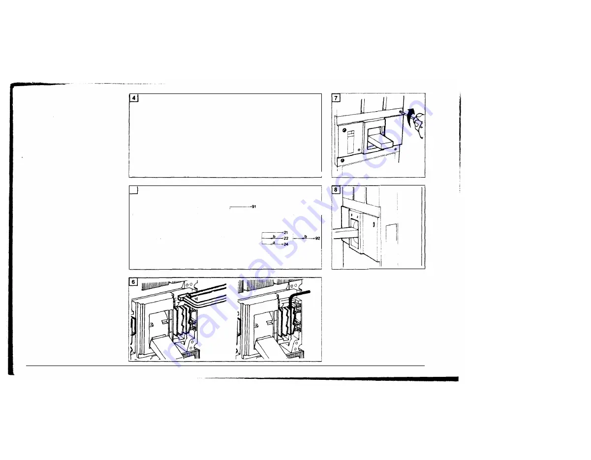
connect wire leads to auxiliary
terminals 1f required
-4 I- auxiliary switch contacts are
closed when circuit breaker is
closed
� 1- alarm switch contacts are
closed when circuit breaker is
tripped
�
auxiliary switch contacts are
open when circuit breaker is
closed
?f"-
alarm switch contacts are
open when circuit breaker is
tripped
(!]
knock out one of the precut
openings depending on the
desired direction of wiring
(see page 7)
Slip the wire leads through this
opening.
m
replace the front cover,
making sure the wire leads are
property routed and will not be
pinched by the cover.
Install the mounting screws
[!]
add accessory identification
and wiring label to left side of the
circuit breaker
12
auxiliary switch
a
•
use a buzzer or light indicator
attached to
11
and
14
terminals
and replace front cover
b
·turn circuit breaker ON.
Indicator light or buzzer should
operate.
alarm switch
a
•
use a buzzer or light indicator
attached to
91
and
94
terminals
and replace front cover
b
•
tum circuit breaker ON.
Trip breaker by pressing the red
push to trip button.
Indicator light or buzzer should
operate.
c-
move breaker handle to ON.
I
Indicator light or buzzer should
remain OFF.
I
5
2 auxiliary
1
auxiliary
+
1
alann
3 auxiliary
+
1
alann
r------11 �31
�12�32
�t4
L.L.--34
,---�31
�" ,.------.
3
1
1
��32 �92
I--IL-12
�--32
�..__34 ��94
�14
��34
�91
:_____..�94
I
I
wl
i
www
. ElectricalPartManuals
. com


