background image

11

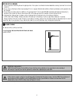
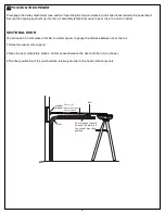
To prevent damage to vehicles, be sure fully open
door provides adequate clearance.

Travel limits regulate the points at which the door will stop

when moving UP or DOWN. The travel limit buttons are located

under the light cover (figure 1).
NOTE: The opener will MOVE AUTOMATICALLY after setting the

DOWN limit at step 6. A complete UP DOWN cycle is performed

in order to “Set the Force” automatically. If the door is

interrupted during this process, the force will not be set and

the process will have to be repeated.

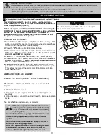
REFER TO THE DIAGRAMS:

1. Turn the Power ON and open the light cover. (The courtesy LEDs

will be on during this operation, and you may need to cover these

in order to see the program buttons clearly).

2. Press the

“P”

button until LED 3 starts flashing.

3. Press and hold the

“+”

button until the door moves to the desired

UP

position.

The “+” and “-” buttons can be used to move the

door UP and DOWN if required.

4. Press the “P” button to set the UP limit. LED 2 starts flashing.

5. Press and hold the

“-”

button until the door moves to the desired

DOWN

position.

The “+” and “-” buttons can be used to move

the door UP and DOWN if required.

6. Press and release the

“P”

button to set the DOWN limit. At this

point the opener will operate AUTOMATICALLY a complete cycle.

This will set the force of the motor, all LED indicators will stop

after this operation.

LIMITS AND FORCE ARE NOW SET.

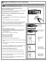
SETTING THE FORCE (MANUAL LEARN IF REQUIRED):

If the limits are already set, the force can be set manually if

required.

1. Start with the door closed.

2. Disconnect the mains power from the opener for approx.10

seconds.

3. Using the remote control, Open and Close the door one complete

cycle.

The Force Setting has now been set manually.

PROGRAM THE TRAVEL LIMITS AND FORCE SETTINGS

ADJUSTMENT SECTION

19

Without a properly installed safety reversal

system, persons (particularly small children)

could be SERIOUSLY INJURED or KILLED by

a closing door.

• Incorrect adjustment of garage door travel limits will

interfere with proper operation of safety reversal

system.

• NEVER use force adjustments to compensate for a

binding or sticking garage door.

• After ANY adjustments are made, the safety reversal

system MUST be tested. Door MUST reverse on

contact with 40 mm high object laid flat on floo

r.

S

P

1

2

3

S

P

1

2

3

S

P

1

2

3

S

P

1

2

3

S

P

1

2

3

1

2

3 2

1

2

3 2

1

2

3 2

1

2

3 2

1

2

3 2

2

3

4

5

6

-

+

P

S

1

3

2

3 2

2 1

-

+

P

S

1

3

2

3 2

2 1

1

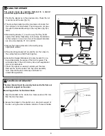
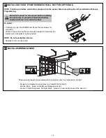
Connect Electric Power

TO AVOID INSTALLATION DIFFICULTIES, DO NOT RUN THE GARAGE DOOR OPENER UNTIL INSTRUCTED TO DO SO.

Connect to properly fused and earthed power outlet.

-

Ensure all ropes and installation tools have been removed from the door.

- When the opener is switched ON, the operator light flashes a number of times and then remains ON.

Summary of Contents for Entrylift MT50EVO

Page 1: ...future reference MT50EVO Sectional Garage Door Opener Installation and Operating Instructions This manual contains IMPORTANT SAFETY information DO NOT PROCEED WITH THE INSTALLATION BEFORE READING THO...

Page 2: ...2014 The Chamberlain Group Inc TM Trademark of The Chamberlain Group Inc Registered Trademark of The Chamberlain Group Inc...

Page 3: ...damp or wet space exposed to weather To avoid damage to very light doors such as fibreglass aluminium or steel doors an appropriate reinforcement should be added To do so contact the door manufacture...

Page 4: ...ce supported entirely by its springs Raise and lower the door to see if there is any binding or sticking 20 kgf is the absolute maximum allowable force to raise or lower the door in any position If yo...

Page 5: ...3 Curved door arm 4 Hanging bracket 2 5 Rail brackets 3 6 Header bracket 7 Door bracket 8 Hardware bag 9 Rail assembly 10 Manual 11 Warning Labels 12 Rail centre bracket Your garage door opener rail...

Page 6: ...oceed with the assembly installation and adjustment procedures in this manual you may find it helpful to refer back to this illustration of a completed installation COMPLETED INSTALLATION 9 4x 8 8x 7...

Page 7: ...when remote controls are not available Open Stop Close 7 LEDs 1 Remote Control Indicator 2 Program DOWN indicator Door Operating Passpoint indicator 3 Program UP indicator No Function Polarity Comment...

Page 8: ...Rail brackets 4 and the screws 5 This completes the assembly of the door opener to the rail FASTEN RAIL TO OPENER 9 10 The segmented rail is largely preassembled and consists of 3 parts The carriage p...

Page 9: ...al lines created in the previous section for proper placement of header bracket A Wall mount centre the header bracket 1 on the vertical centre line 2 with the bottom edge of the header bracket on the...

Page 10: ...etween door and rail 1 Raise the opener onto support 2 Open the door completely place a 50 mm spacer between the door and the rail as shown 3 The final positioning of the rail should be relatively par...

Page 11: ...ge is not obstructed The carriage can not pass through the bracket Mounting at the very back fig B is ideal 3 Bend ceiling fixtures 1 in such a way that they lie flat against the ceiling Depending on...

Page 12: ...opener is installed the handle should be no higher then 1 8 metres from the floor The cord may need to be extended Attach the manual release Instruction Label to the cord as indicated in fig 1 DO NOT...

Page 13: ...e force of the motor all LED indicators will stop after this operation LIMITS AND FORCE ARE NOW SET SETTING THE FORCE MANUAL LEARN IF REQUIRED If the limits are already set the force can be set manual...

Page 14: ...erse test When the door reverses off the 40 mm obstacle remove the obstacle and run the opener through a complete travel cycle Door must not reverse in closed position If it does repeat Program the Li...

Page 15: ...e floor Attach bracket assemblies with carriage bolts as shown Adjust right and left side bracket assemblies to the same distance out from mounting surface Make sure all door hardware obstructions are...

Page 16: ...22 1 service www chamber a n de nfo chamber a n de B B A 2 114A3361 For Service Call Installation Date 3 132A2900 RISK OF ENTRAPMENT Repeat Safety Reverse Test monthly Door must reverse on contact wit...

Page 17: ...opener 2 Press and release the S button The LED 1 indicator light will glow steadily 3 Enter a 4 digit personal identification number PIN of your choice on the keypad 4 Press and hold the ENTER button...

Page 18: ...If it is unbalanced or binding call a qualified door technician Check to be sure door opens closes fully Adjust limits and or force if necessary Repeat the safety reverse test Make any necessary adjus...

Page 19: ...mote control 5 Model E940M 1 Channel visor remote control 6 Model E943M 3 Channel visor remote control 7 Model E945M 3 Channel mini remote control 8 Model E840M Keyless entry system 9 Model C77 The Pr...

Page 20: ...ersons in order to avoid hazard RAIL REPLACEMENT PARTS 041A4017 Motor shaft adapter PVC 041A4021 Trolley latch chain 041A4016 Position tab chain 041A4001EV Logic Board 041A4024 Transformer 041A4033 Mo...

Page 21: ...process and may have dislodged 1 Opener doesn t operate from either door control or remote Does the opener have electric power Plug lamp into outlet If it doesn t light check the fuse box or the circ...

Page 22: ...3 min Door Linkage Adjustable door arm Pull cord trolley release Safety Personal Push button stop in UP and DOWN direction Automatic safety reverse in both UP and DOWN direction Electronic Automatic...

Page 23: ...aler will provide you with either repairs to the Unit or a replacement Unit Repairs and replacement parts provided under this Chamberlain Limited Warranty are provided free of charge and are warranted...

Page 24: ...TM Trademark of The Chamberlain Group Inc Registered Trademark of The Chamberlain Group Inc Warranty Registration To validate your warranty you must complete the registration form online at gomerlin...

Reviews: