8-30
10 July 1998
All filters in the ISP-100 are derived from analog prototypes. The
analog filters are approximated by the Bilinear Transform method,
prewarped to match response at the critical frequency appropriate for
the type of filter (cutoff frequency for LowPass/HighPass and Peaked
HighPass; hinge frequency for LowShelf/HighShelf; center frequency
for all others).
Each filter band may be bypassed; so as to pass the signal
unaltered.
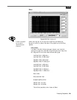
LowPass Filters
LowPass Filters pass low frequencies and stop high frequencies.
Since it is not realistically possible to create a perfect filter that
passes low frequencies totally unaltered and stops high frequencies
completely, lowpass filter design involves compromises that allow
some rounding of the corner at the filter cutoff frequency and some
slope in the transition to the high frequency stopband. Different
compromise schemes are given different names; the ISP-100
incorporates Bessel, Butterworth, and Linkwitz-Riley lowpass filter
types.
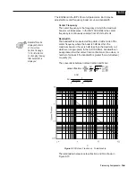
The cutoff frequency is defined as the frequency at which the
magnitude of the filter response has fallen to -3 dB relative to the
unfiltered signal in the Bessel and Butterworth types, and to -6 dB in
the Linkwitz-Riley types. In the ISP-100 lowpass filters the cutoff
frequency is continuously variable from 20Hz to 20 kHz.
In the ISP-100 lowpass filters the passband slope is selectable from
-6 dB/octave to -12 dB/octave for the Bessel and Butterworth types.
NOTE: Linkwitz-Riley filters are also known as Butterworth-Squared
filters because they are the product of two Butterworth filters. A -12
dB/octave Linkwitz-Riley lowpass filter may be constructed by
cascading two identical -6 dB/octave Butterworth lowpass filters; a -
24 dB/octave Linkwitz-Riley lowpass filter may be constructed by
cascading two identical -12 dB/octave Butterworth lowpass filters.
HighPass Filters
HighPass Filters pass high frequencies and stop low frequencies.
Since it is not realistically possible to create a perfect filter that
passes high frequencies totally unaltered and stops low frequencies
completely, highpass filter design involves compromises that allow
some rounding of the corner at the filter cutoff frequency and some
slope in the transition to the low frequency stopband. Different
compromise schemes are given different names; the ISP-100
incorporates Bessel, Butterworth, and Linkwitz-Riley lowpass filter
types.
The cutoff frequency is defined as the frequency at which the
magnitude of the filter response has fallen to -3 dB relative to the
unfiltered signal in the Bessel and Butterworth types, and to -6 dB in
the Linkwitz-Riley types. In the ISP-100 highpass filters the cutoff
frequency is continuously variable from 20Hz to 20 kHz.
Summary of Contents for Integrated Signal Processor ISP-100
Page 1: ...User s Manual ISP 100 INTEGRATED SIGNAL PROCESSOR...
Page 2: ...THIS PAGE LEFT BLANK INTENTIONALLY...
Page 24: ...2 10 10 July 1998 THIS PAGE LEFT BLANK INTENTIONALLY...
Page 32: ...3 8 10 July 1998 THIS PAGE LEFT BLANK INTENTIONALLY...
Page 48: ...5 6 10 July 1998 THIS PAGE LEFT BLANK INTENTIONALLY...
Page 126: ...A 4 10 July 1998 THIS PAGE LEFT BLANK INTENTIONALLY...
Page 128: ...B 2 10 July 1998 MONDOEQ QMS...
Page 129: ...B 3 Standard QuickMAPs 2X6CMBC QMS...
Page 130: ...B 4 10 July 1998 2X8COMB QMS...
Page 131: ...B 5 Standard QuickMAPs 3X6CMBC QMS...
Page 132: ...B 6 10 July 1998 2X8THRU QMS...
Page 133: ...B 7 Standard QuickMAPs 4CHAN QMS...
Page 134: ...B 8 10 July 1998 4X6CMBC QMS...
Page 135: ...B 9 Standard QuickMAPs 4X6THRU QMS...
Page 136: ...B 10 10 July 1998 3_2W QMS...
Page 137: ...B 11 Standard QuickMAPs 2WAYS QMS...
Page 138: ...B 12 10 July 1998 2_3WAY QMS...
Page 139: ...B 13 Standard QuickMAPs 2_2W_SUB QMS...
Page 140: ...B 14 10 July 1998 2_2W_FR QMS...
Page 141: ...B 15 Standard QuickMAPs 2_2W_2ST QMS...
Page 142: ...B 16 10 July 1998 4_2WAYS QMS...
Page 143: ...B 17 Standard QuickMAPs 4W_2FR QMS...
Page 144: ...B 18 10 July 1998 LCR QMS...
Page 145: ...B 19 Standard QuickMAPs MONO3W QMS...

