background image

3-2

10 July 1998

Diagnostics

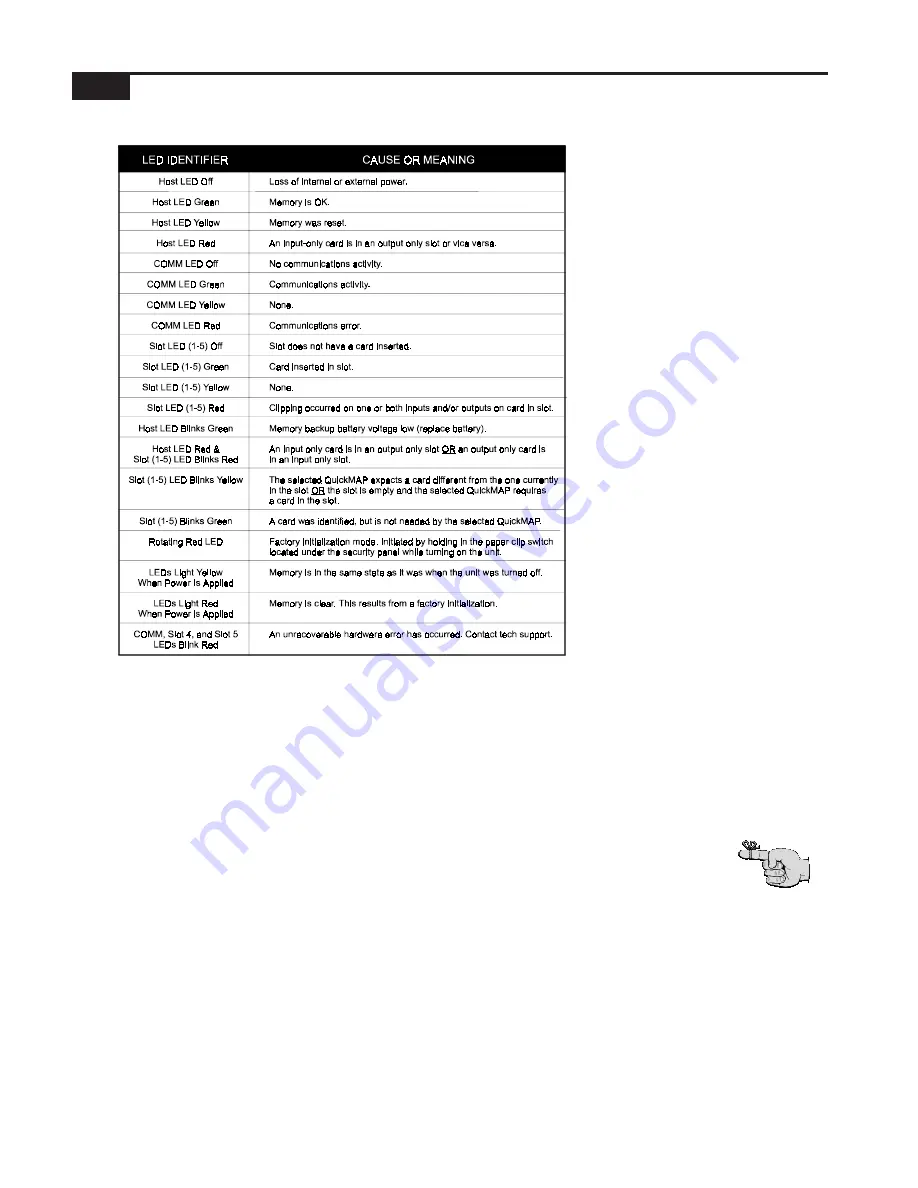
Table 3-1 LED diagnostic messages.

The ISP-100 was designed with built-in diagnostics that activate when
power is applied to the unit. During the power-up cycle, the ISP-100
performs several self-checks. The ISP-100 also will report problems, as
they happen, while the unit is running. The diagnostic messages are
communicated through the front panel LEDs. Refer to Table 3-1 for a list
of common LED conditions and corresponding diagnostic messages.

Factory Default Mode

A yellow host LED indicates factory default mode. This mode usually
results from either an OS update or memory erasure. When in this
mode a default QuickMAP and QuickSET are loaded that prevents the
unit from passing damaging signals. The QuickMAP configures the
ISP-100 as a straight through processor with high pass filters on the
outputs. The corner frequencies of the high pass filters are set to
20 kHz.

To enter factory default mode, hold in the default switch (see Figure
2-1, item 6) while turning on the power. Continue to hold in the switch
until the front panel LEDs turn red and begin to rotate.

Note that when the

factory default

QuickMAP is loaded

one or more slot

LEDs may blink

yellow. This is normal

operation and not

an error.

Summary of Contents for Integrated Signal Processor ISP-100

Page 1: ...User s Manual ISP 100 INTEGRATED SIGNAL PROCESSOR...

Page 2: ...THIS PAGE LEFT BLANK INTENTIONALLY...

Page 3: ...User Environmental for InterActive Technology are trademarks of TELEX Communications Windows Windows 3 1 Windows 3 11 Windows 95 and MS DOS are all trademarks of Microsoft Corporation Names of other p...

Page 4: ...MENT DIRECTLY TO THE FACTORY WITHOUT FIRST OBTAINING A RETURN AUTHORIZATION Be prepared to provide the company name address phone number a person to contact regarding the repair the type and quantity...

Page 5: ...which it was installed 2 Restrictions a You may not market distribute or transfer copies of the Software to others or electronically transfer or duplicate the Software YOU MAY NOT REVERSE ENGINEER DE...

Page 6: ...iagrams 2 4 Analog Audio 2 4 Digital Audio 2 5 Serial Communications 2 6 General Purpose Inputs GPI 2 9 Master Sync Input 2 9 TROUBLESHOOTING 3 1 User Modifications 3 1 In Case of Problems 3 1 Diagnos...

Page 7: ...ter 4 4 Shelving Filter 4 4 System Measurements 4 5 System Frequency Response 4 5 System Noise Floor 4 5 System THD N 4 5 MIM 1 MIM 2 Analog Input Modules 4 6 Power 4 6 Performance 4 6 Miscellaneous 4...

Page 8: ...uickMAP Template Files 6 4 Component Directory 6 4 Operating System OS Files 6 4 USING VUE IT 7 1 File 7 1 New Project 7 1 Open Project 7 1 Save 7 1 Save As 7 1 Activate Project Manager 7 1 Activate Q...

Page 9: ...t Properties 7 8 Component Export 7 9 Component Import 7 10 QuickSET Manager 7 10 Creating New QuickSETs 7 11 Deleating QuickSETs 7 11 Selecting the Active QuickSET 7 11 Updating a QuickSET 7 11 Disca...

Page 10: ...ers 8 13 Four Way Crossovers 8 17 Sum to Allpass Characteristics of Linkwitz Riley Crossovers 8 20 Low Low Mid Mid Mid High and High Controls 8 21 Link Unlink Control 8 21 Slope 8 21 Class 8 22 Cutoff...

Page 11: ...e Logarithmic Log or Linear Control 8 37 Using the 24 dB 40 dB 120 dB Controls 8 37 Gain Trim 8 37 Fine F or Coarse C Control 8 38 Isolate Iso Control 8 38 Polarity Control 8 38 Gain 8 39 Metering 8 3...

Page 12: ...48 Notes on Operation of the Limiter 8 49 Meter 8 50 Threshold 8 50 Attack Window Release and Crest Factor Controls 8 51 Fine F or Coarse C Control 8 51 Knee Control 8 51 Bypass Control master 8 51 Se...

Page 13: ...y is greatly increased An ergonomically designed software interface called VUE IT provides graphic control panels with the conventional look of signal processors as well as an advanced and easy to use...

Page 14: ...user friendly as possible However this manual should be read before attempting to install or operate the ISP 100 Customer Support Be sure to fill out the customer support registration card included in...

Page 15: ...EC Power Cord Front Panel Features see Figure 2 1 Figure 2 1 ISP 100 front panel features 1 Label Holder Provides a space to indicate the assignments of the input and output modules 2 Status LEDs Prov...

Page 16: ...r an analog output module or digital module 7 Output Slot 3 Accepts either an analog output module or digital module 8 Input Output Slot 2 Accepts an analog input module analog output module or digita...

Page 17: ...igure 2 3 for more information 6 Being careful to avoid scraping the underside of the board slide the new module into the bottom slots on the card guides located inside the opening Push the module int...

Page 18: ...XLR connector and the shield wire to pin 1 of the connector To avoid a 6 dB drop in level connect pin 3 to pin 1 of the connector See Figure 2 6 for more information Figure 2 7 Analog outputs Balanced...

Page 19: ...able such as MOGAMI 3080 See Figure 2 8 for more information SPDIF Input Figure 2 9 SPDIF inputs Connect the positive side of the line to pin 2 of the male 3 pin XLR connector and the shield of the ca...

Page 20: ...gh the DB 9 connector located under the front panel security cover or through the RJ 45 connector located on the rear panel The computer connected to the ISP 100 must have a free COM port 1 4 Communic...

Page 21: ...cifications for RS 232 communications allow for connections up to 50 feet For longer connections the RS 232 signals must be converted to a standard such as RS 485 that is tolerant of long distances Th...

Page 22: ...signal pinouts for RJ 45 DB 9 and DB 25 connectors Figure 2 16 Connector pinouts The RS 232 standard is very common to computer controlled devices Table 2 1 and Figure 2 16 can help you decipher the...

Page 23: ...to external from the Properties for Merlin ISP 100 panel in the VUE IT software See Figure 2 18 and page 7 6 of this manual for more information Dry i e switch or electronic i e open collector contac...

Page 24: ...2 10 10 July 1998 THIS PAGE LEFT BLANK INTENTIONALLY...

Page 25: ...red under warranty or otherwise In Case of Problems Check the following items Verify that the unit is properly connected to an AC power source and the source is active Check the fuse Verify that the i...

Page 26: ...dicates factory default mode This mode usually results from either an OS update or memory erasure When in this mode a default QuickMAP and QuickSET are loaded that prevents the unit from passing damag...

Page 27: ...Manager and then clicking on the Properties button will reveal the ISP 100 s serial number See Figure 3 2 Application OS and DSP version numbers can be obtained by clicking on the Help menu and then...

Page 28: ...panel has an expected life of four years If the Host LED is blinking the battery needs to be changed CAUTION The battery used in this device may present a risk of fire or chemical burn if mistreated D...

Page 29: ...ri Eksplosionsfare ved feijlagtig handtering af samme fabrikat og type Lever det brugte batteri tilbage till leverandoren FINLAND VAROITUS Paristo voi rajahtaa jos se on virheellisesti asennettu Vaihd...

Page 30: ...PC operating system used 7 COM port used 8 PC type and amount of memory installed Procedure for Returns If a repair is necessary contact the dealer where this unit was purchased If repair through the...

Page 31: ...e container is used the equipment should be wrapped in paper and surrounded with at least four inches of excelsior or similar shock absorbing material All shipments must be sent to the following addre...

Page 32: ...3 8 10 July 1998 THIS PAGE LEFT BLANK INTENTIONALLY...

Page 33: ...quency 20 Hz to 20 kHz Depends 1 12 Oct 1 3 Oct Gain 0 dB to 96 dB 0 dB 0 5 dB 1 dB Absolute Polarity n a n a Delay Property Range Default Fine Coarse Delay 0 ms to 2 7 s 0 ms 02 ms 1 ms Dither Proper...

Page 34: ...terworth Butterworth n a n a or Linkwitz Riley HighPass Filter Property Range Default Fine Coarse Slope 6 12 12 n a n a Cutoff Frequency 20 Hz to 20 kHz 20 1 12 Oct 1 3 Oct Class Bessel Butterworth Bu...

Page 35: ...el 2 Entry Gain 0 dB to 96 dB 0 dB 5 dB 1 dB Channel 2 Entry Polarity n a n a Input Property Range Default Fine Coarse Left Gain A 0 2 4 8 dB 0 dB n a n a Right Gain B 0 2 4 8 dB 0 dB n a n a Left Pad...

Page 36: ...4 4 10 July 1998 Gate Linkwitz Riley 3 way Crossover Notch Filter Parametric Equalizer Filter Peaked HighPass Filter Shelving Filter AP is a trademark of Audio Precision Inc...

Page 37: ...4 5 Specifications System Measurements System Frequency Response System Noise Floor System THD N AP is a trademark of Audio Precision Inc...

Page 38: ...7 0 05 0 25 dB Z in Input Impedance 8 11000 12000 13500 ohms Operating Temperature 50 75 100 F Operating Humidity 20 50 80 Miscellaneous Overall Size 9 8 40 long by 2 55 wide by 1 50 high Weight 4 0 o...

Page 39: ...0 degrees Output Balance 0 5 dB Gain Accuracy 5 0 05 0 25 dB Z out Output Impedance 6 594 600 606 ohms Operating Temperature 50 75 100 F Operating Humidity 20 50 80 Miscellaneous Overall Size 8 40 lon...

Page 40: ...put Data 2 THD N Total Harmonic Distortion 0 00002 0 00016 plus Noise 3 RELATIVE IMD Intermodulation Distortion 4 TBD SMPTE 4 1 Jitter in Output Clock 5 415 pS 700 Hz 100KhZ Tolerable Jitter in Input...

Page 41: ...dard female XLR Output Connector 3 Pin standard male XLR XLR pinout Pin 1 shield Pin 2 positive input Pin 3 negative input Input Data Format AES EBU AES3 Professional and S PDIF IEC958 Consumer data f...

Page 42: ...fore being applied to the sample rate converter 15 Must be derived from MCLK 16 Must be derived from MCLK 17 Must be derived from MCLK 18 Must be derived from MCLK 19 Must be nominally 48 kHz when ins...

Page 43: ...ports that is currently being used or install an additional serial port If you are unfamiliar with this please contact your local computer dealer for assistance NOTE It may be necessary to remove devi...

Page 44: ...as those in Figures 5 1 and 5 2 usually indicates this The procedure is as follows 1 Make sure both the computer and the ISP 100 are both turned off 2 Connect the computer to the ISP 100 3 Hold in the...

Page 45: ...rogress dialog 6 The lights will continue to rotate with only brief pauses You will also see a progress indicator on the PC s screen similar to the one in Figure 5 4 7 When the download is complete th...

Page 46: ...ectories used and enter information such as the company s and designer s names It is recommended that you do not change the directory names unless you are an experienced user and know the implications...

Page 47: ...ry selecting a different serial port Figure 5 9 Communications error dialog If a dialog box similar to the one in the Figure 5 9 appears then a serial port that does not exist has been selected Anothe...

Page 48: ...5 6 10 July 1998 THIS PAGE LEFT BLANK INTENTIONALLY...

Page 49: ...he menu names are short cut buttons that provide access to common commands via a single mouse click The buttons are from left to right New Project Open Project Save Project Revert Scan Project Manager...

Page 50: ...the diamond to the left of either the Build from Script or Upload from ISP 100 options The Build from Script option uses files stored on your hard drive to create the QuickMAP The Upload from ISP 100...

Page 51: ...uickMAP has been created three panels will appear on the screen They are Project Manager QuickSET Manager and QuickMAP See Figure 6 4 VUE IT File System When a new project is created a number of files...

Page 52: ...ory C PROGRAMFILES VUE IT ISP 100 QMAPS The QuickMAP template file location is important to users who either have access to QuickMAP creation software or have been sent a new QuickMAP not contained in...

Page 53: ...project under another name Activate Project Manager Opens the project manager window after it has been closed Activate QuickSET Manager Opens the QuickSET Manager window after it has been closed This...

Page 54: ...ee Figure 7 3 Figure 7 4 Options menu Preferences Allows the user to setup preferences available within VUE IT System Configurations Allows the user to setup project directories company name designer...

Page 55: ...6 Figure 7 6 Help menu About Lists the current application software version OS version and DSP version if an ISP 100 is connected and online If an ISP 100 is not online only the application software...

Page 56: ...s message is received the status panel is automatically opened Display QuickMAP pop up names If selected the pop up component nametags in the QuickMAP layout display are shown Display Filter Bandwidth...

Page 57: ...fline on the PC will be used for communications with the ISP 100 Once a new COM port is selected you may need to select Scan from the Tools menu in order for the software to identify an ISP 100 connec...

Page 58: ...ference frequency AES EBU only 4 External Reference 12 288 6 144 or 3 072 MHz via external input BNC An error will be returned if either slot 1 or slot 2 is selected as the clock master while the slot...

Page 59: ...selection dialog QuickMAP Selection see Figure 7 12 is where a project s QuickMAP is chosen It appears when the Build From Script option is selected when setting up a new project Here you will be able...

Page 60: ...ckMAP Properties Figure 7 12 QuickMAP properties dialog QuickMAP Properties see Figure 7 13 appear by clicking on the QuickMAP entry in the Project Manager and then clicking on the Properties button F...

Page 61: ...the lower left corner of the dialog These files can be sorted by clicking on the Name Type and Group heading buttons The first mouse click on one of these buttons will sort the list in ascending orde...

Page 62: ...t dialog displays currently existing component presets filenames in the upper half of the dialog box These files can be sorted by clicking on the Name Type Group and Mod Time heading buttons The first...

Page 63: ...ing Update overwrites the information previously saved in the selected QuickSET Discarding Changes The Revert button allows the user to make changes to a QuickSET and then go back to the original sett...

Page 64: ...T Increment Contact closure causes the next QuickSET stored in memory to be loaded into the QuickMAP QuickSET Decrement Contact closure causes the previous QuickSET stored in memory to be loaded into...

Page 65: ...mponent onto a component of the same type and releasing the mouse button will copy the component settings from the component being dragged to the component it is dropped on QuickMAP Component Bypassin...

Page 66: ...ontrol This button controls the tracking of the Gain Attenuator levels If the LED is gray then the two channels do not track each other If the LED is blue then the channels track each other Clicking o...

Page 67: ...row next to the number in the text box A selection list will appear The list may or may not be scrollable Click on the desired entry to make a selection Digital I O In Mute RX Mutes the AES receiver d...

Page 68: ...hat the digital receiver has detected an AES EBU formatted data stream Consumer indicates that the digital receiver has detected an SPDIF formatted data stream Input Stream Emphasis Emphasis indicates...

Page 69: ...s being used and no Sample Rate Converter is selected Card position dependent 3 Non Audio Input Stream Card position dependent 4 Slot Cannot be chosen as master and have sample rate converter present...

Page 70: ...Meters see Figure 7 24 provide monitoring of the outputs of the DSPs before digital to analog conversion To activate the Meters click on the green output triangles in the QuickMAP or click on the Met...

Page 71: ...nderstand the inner workings of the component References to specific journal articles and other supplementary sources are provided for further reading An explanation of how to manipulate the various c...

Page 72: ...sing the Knob Click on the indicator on the knob and while continuing to hold down the mouse button move the mouse in an arc The numbers in the box below the knob will change When the desired level is...

Page 73: ...gnal s phase will be changed 180 Clicking on the button will toggle the setting Mute Control M This button determines if the input signal will be muted A black M indicates that the signal is not muted...

Page 74: ...ts the amount by which the output signal level changes for a given change in input signal level When compressing the output level change in dB will be equal to the input level change in dB divided by...

Page 75: ...sor allows the output signal level to also decrease but only as much as is appropriate for the selected compression ratio setting A compressor generally sounds better if it is forced to ramp the outpu...

Page 76: ...rwise the appropriate other channel should be selected from the set of available Sidechain Sources in the menu Unfamiliar Controls There are two controls on the ISP 100 compressor that are not availab...

Page 77: ...s the peak level of each input sample The peak level is multiplied by the setting of the Crest Factor Sensitivity control which is always a number between zero and one The two quantities are then comp...

Page 78: ...lower the threshold the greater the overshoot This represents normal operation for the compressor Computation of Average Level There are two common methods of computing average signal level one is bas...

Page 79: ...vely click and drag across the number in the box to highlight the number in it Type the new setting and press the Enter key when finished Using the UP DOWN Arrows To increase the level click on the up...

Page 80: ...m inactive to active A Hard knee causes the response by the component to be abrupt while a Soft knee causes a gentle response Clicking on the button will toggle the setting Ratio Control To change set...

Page 81: ...y crossovers may exist Each of these crossovers may be implemented using Bessel or Butterworth filters with 1st through 4th order slopes or Linkwitz Riley filters with 2nd or 4th order slopes or combi...

Page 82: ...be bypassed in which case all of the crossover filters in that band will be bypassed while the crossover filters in the other band will not be affected Two Way Bessel and Butterworth Crossovers Bessel...

Page 83: ...ave Linkwitz Riley crossover is characterized by 4th order Linkwitz Riley Butterworth Squared lowpass filter 6 dB magnitude response at crossover frequency 4th order Linkwitz Riley Butterworth Squared...

Page 84: ...tterworth Squared 12 dB octave 2nd order Linkwitz Riley Butterworth Squared 24 dB octave 4th order In addition the cutoff frequency attenuation and polarity in the low band the mid band and the high b...

Page 85: ...Bessel filters used in the ISP 100 crossovers are automatically scaled so that their amplitude response is 3 dB at the selected cutoff frequency regardless of the filter order The amplitude response...

Page 86: ...s band opposite that of lowpass band In a 3 way crossover the bands associate in non obvious ways see Sum to Allpass Characteristics of Linkwitz Riley Crossovers and the polarity reference for the hig...

Page 87: ...for the optional LP2 and the highpass filters HPx except for the optional HP2 may each be independently configured as Bessel 6 dB octave 1st order Bessel 12 dB octave 2nd order Bessel 18 dB octave 3rd...

Page 88: ...group delay meaning that they have nearly linear phase and excellent transient response Their amplitude response is not as flat and their cutoff is not as sharp as those of Butterworth filters Butterw...

Page 89: ...gh band the 1 allpass filter in the mid high band the 3 allpass filter in the low mid band and the LP2 lowpass filter and 3 allpass filter in the low band The inclusion of these filters is mandatory f...

Page 90: ...Linkwitz Riley crossover is characterized by 4th order Linkwitz Riley Butterworth Squared lowpass filter 6 dB magnitude response at crossover frequency 4th order Linkwitz Riley Butterworth Squared hig...

Page 91: ...D Low Low Mid Mid Mid High and High Controls The Low Low Mid Mid Mid High and High buttons determine if that section of the crossover is bypassed If the word Low Low Mid Mid Mid High or High is displa...

Page 92: ...ished Using the UP DOWN Arrows To increase the level click on the up arrow To decrease the level attenuation click on the down arrow The amount of increase or decrease is controlled by the fine coarse...

Page 93: ...the setting Polarity Control This button determines the polarity of the signal A indicates that the signal will not have it s phase altered A indicates that the signal s phase will be changed 180 Clic...

Page 94: ...Attenuator The attenuator can be set three ways Using the Knob Click on the indicator on the knob and while continuing to hold down the mouse button move the mouse in an arc The numbers in the box be...

Page 95: ...al s phase will be changed 180 Clicking on the button will toggle the setting Mute Control M This button determines if the input signal will be muted A black M indicates that the signal is not muted w...

Page 96: ...e the setting to return to the number that it was before a change was attempted Alternatively click and drag across the number in the box to highlight the number in it Type the new setting and press t...

Page 97: ...nd the original signal Final Signal Error Signal Original Signal When audio data words are shortened by simple truncation it turns out that the error signal is correlated with itself and with the orig...

Page 98: ...dB octave slope in the audio band The dither signal used in the ISP 100 has a triangular probability density function TPDF for the minimization of noise modulation effects Bypass Bypassing dither res...

Page 99: ...DSP code Each band can be configured as one of seventeen different filter types LowPass Filter 6 dB octave LowPass Filter 12 dB octave HighPass Filter 6 dB octave HighPass Filter 12 dB octave LowShel...

Page 100: ...equency is continuously variable from 20Hz to 20 kHz In the ISP 100 lowpass filters the passband slope is selectable from 6 dB octave to 12 dB octave for the Bessel and Butterworth types NOTE Linkwitz...

Page 101: ...anged by approximately 3 dB relative to the unfiltered signal In the ISP 100 lowshelf filters the hinge frequency is continuously variable from 20Hz to 20 kHz In the ISP 100 lowshelf filters the trans...

Page 102: ...it is not realistically possible to create a perfect filter that stops one frequency completely and passes all other frequencies totally unaltered notch filter design involves compromises that allow s...

Page 103: ...than the maximum boost or the cut is 3 dB less than the maximum cut whichever is appropriate In the ISP 100 filters bandwidth can be expressed in either octave fraction fractions of an octave or numbe...

Page 104: ...eak magnitude at approximately the selected cutoff frequency and then returns to a 12 dB octave rolloff characteristic below Peak Magnitude In the ISP 100 Peaked HighPass filter the peak magnitude of...

Page 105: ...ency is continuously variable from 20 Hz to 20 kHz Filter Type To change settings click on the arrow next to the entry in the text box A selection list will appear The list may or may not be scrollabl...

Page 106: ...nd enters the new level Be sure to press the Enter key after the entry is made Clicking outside the text box without pressing the Enter key will cause the setting to return to the number that it was b...

Page 107: ...the setting Using the 24 dB 40 dB 120 dB Controls These buttons allow the user to view the composite filter response in three different dynamic ranges Clicking on one of the buttons will set the dynam...

Page 108: ...o Control This button allows the user to toggle between viewing either the composite response of all active filters in the filter bank or the composite response of an individual filter Clicking on the...

Page 109: ...levels as the peak level of a signal can exceed its average by a tremendous amount The advantage of true peak indicating meters in a digital signal processor like the ISP 100 lies in their ability to...

Page 110: ...empted Alternatively click and drag across the number in the box to highlight the number in it Type the new setting and press the Enter key when finished Using the UP DOWN Arrows To increase the level...

Page 111: ...8 41 Processing Components Gain i e after the master attenuator A green LED indicates that the meter information is pre fader Clicking on the button will toggle the setting...

Page 112: ...e no attenuation is applied and the level of the output signal exactly matches the level of the input signal When the average input signal is below the threshold value attenuation is applied and the l...

Page 113: ...riate other channel should be selected from the set of available Key Channels in the menu Unfamiliar Controls There are two controls on the ISP 100 gate that are not available in traditional noise gat...

Page 114: ...he level reported by the gate may differ slightly from the RMS value expected for a given signal Keying from Other Channels When the key channel input to a ISP 100 gate is selected to be a channel oth...

Page 115: ...t box without pressing the Enter key will cause the setting to return to the number that it was before a change was attempted Alternatively click and drag across the number in the box to highlight the...

Page 116: ...e threshold value no limiting takes place and the change in level of the output signal exactly matches the change in level of the input signal When the input signal level is above the threshold value...

Page 117: ...ng below the threshold to limiting above Under soft knee conditions the output level and the input level track until approximately 12 18 dB below the threshold beyond which they slowly begin to diverg...

Page 118: ...r detection windows Detection Window is adjustable in the range 20 uSec one sample to 5 Sec Crest Factor Sensitivity A signal s crest factor is the ratio of a its peak level to its average level The s...

Page 119: ...actor Sensitivity control so that the limiter responds appropriately to short signal peaks If it were possible to know in advance what the crest factor of the input signal was going to be then the Cre...

Page 120: ...s must still be set The sidechain selects only the channel s data not its limiter control settings If multiple limiters utilize the same channel as their sidechain sources then all controls on all lim...

Page 121: ...ing and press the Enter key when finished Using the UP DOWN Arrows To increase the level click on the up arrow To decrease the level attenuation click on the down arrow The amount of increase or decre...

Page 122: ...available sources is determined by the QuickMAP and not the hardware configuration For example A particular QuickMAP has three source selects in it This will require two input cards The user is only a...

Page 123: ...ose output voltage is fixed at a value for all input voltages higher than a predetermined value Clippers can flat top the positive negative or both positive and negative peaks of an input voltage Clip...

Page 124: ...gnal or force is applied or removed and the instant at which a circuit or device subsequently responds in a specified manner Dither The reduction of bits in a digital audio signal for use on a target...

Page 125: ...a wavelength or in electrical degrees Polarity See PHASE SHIFT QuickMAP The diagram outlining the processing components in a particular processing setup QuickSET The group of component settings assoc...

Page 126: ...A 4 10 July 1998 THIS PAGE LEFT BLANK INTENTIONALLY...

Page 127: ...e word IN or OUT is followed by a number 1 5 and a letter A or B The number indicates the slot which is used and the letter indicates the connector used For example IN 1A would indicate that it is an...

Page 128: ...B 2 10 July 1998 MONDOEQ QMS...

Page 129: ...B 3 Standard QuickMAPs 2X6CMBC QMS...

Page 130: ...B 4 10 July 1998 2X8COMB QMS...

Page 131: ...B 5 Standard QuickMAPs 3X6CMBC QMS...

Page 132: ...B 6 10 July 1998 2X8THRU QMS...

Page 133: ...B 7 Standard QuickMAPs 4CHAN QMS...

Page 134: ...B 8 10 July 1998 4X6CMBC QMS...

Page 135: ...B 9 Standard QuickMAPs 4X6THRU QMS...

Page 136: ...B 10 10 July 1998 3_2W QMS...

Page 137: ...B 11 Standard QuickMAPs 2WAYS QMS...

Page 138: ...B 12 10 July 1998 2_3WAY QMS...

Page 139: ...B 13 Standard QuickMAPs 2_2W_SUB QMS...

Page 140: ...B 14 10 July 1998 2_2W_FR QMS...

Page 141: ...B 15 Standard QuickMAPs 2_2W_2ST QMS...

Page 142: ...B 16 10 July 1998 4_2WAYS QMS...

Page 143: ...B 17 Standard QuickMAPs 4W_2FR QMS...

Page 144: ...B 18 10 July 1998 LCR QMS...

Page 145: ...B 19 Standard QuickMAPs MONO3W QMS...

Page 146: ...7 98 P N 38109 744 Rev A Copyright 1997 98 TELEX Communications Inc All Rights Reserved Printed in USA 9600 Aldrich Avenue South Minneapolis MN 49107 USA Ph 612 884 4051 Fax 612 887 5588...

Reviews: