8-27
Processing Components - Dither
Dither
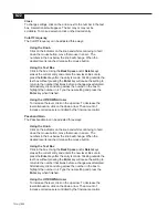
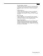
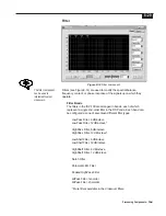
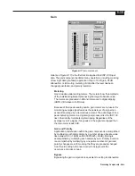
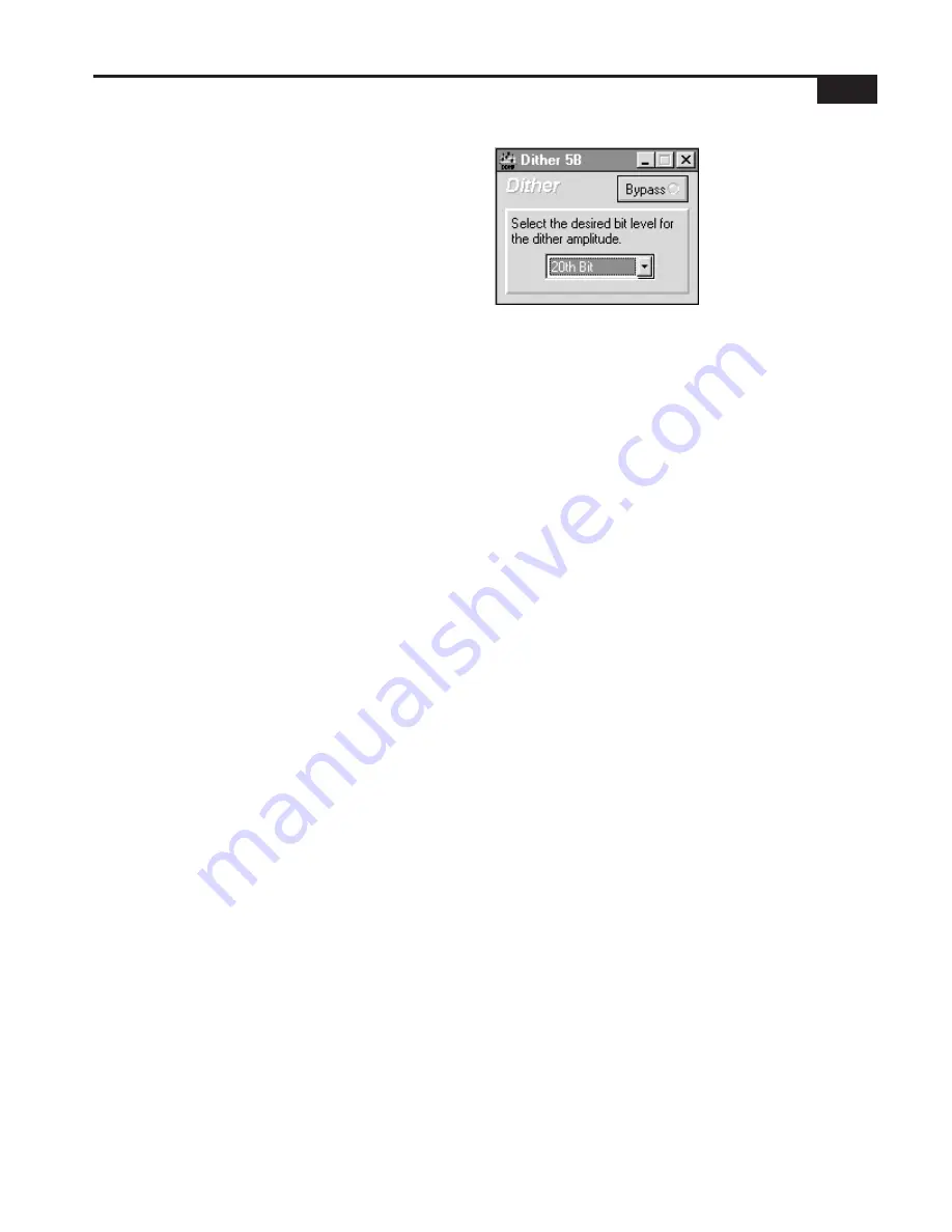
Figure 8-13 Dither component.
Dithering (see Figure 8-13) is used when shortening high resolution
digital audio data words to a lower resolution; for example, when sending
24-bit ISP-100 audio data to 20-bit D/A converters, or directly to a 16-bit
Digital Audio Tape recorder through a digital interface. Simply truncating,
or discarding, the unused bits results in audible artifacts that are
generally objectionable. Dithering does not eliminate these artifacts, it
changes their characteristics so that they are less noticeable to the
human ear.
If, after reducing the number of bits in a signal, the original high-
resolution (more bits) signal is subtracted from the final lower-resolution
(fewer bits) signal, the difference is called the error signal:
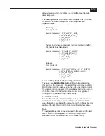
(Final Signal) - (Original Signal) = (Error Signal)
Some very simple algebra shows that the final signal can be thought of
as the sum of the error signal and the original signal:
(Final Signal) = (Error Signal) + (Original Signal)
When audio data words are shortened by simple truncation, it turns out
that the error signal is correlated with itself and with the original signal.
This simply means that the error signal is not pure white noise, and that
the frequency and amplitude of the error signal is in some way related to
the frequency and amplitude of the original signal.
If noise with some very specific amplitude and spectral characteristics is
added to the original signal before truncation, then the correlation is
destroyed and the error signal sounds like low level noise instead of
tones. Even though the added noise actually raises the noise floor in the
final low-resolution signal, it sounds better because human hearing finds
low level broadband noise to be much less objectionable than spurious
tones.
This addition of noise before truncation is called dithering. The noise that
is added is called the dither signal.
In summary, dithering is a way of making digital audio better by making it
worse.
Bit Level
In the ISP-100 the bit level of the dither signal is selectable as whole
Summary of Contents for Integrated Signal Processor ISP-100
Page 1: ...User s Manual ISP 100 INTEGRATED SIGNAL PROCESSOR...
Page 2: ...THIS PAGE LEFT BLANK INTENTIONALLY...
Page 24: ...2 10 10 July 1998 THIS PAGE LEFT BLANK INTENTIONALLY...
Page 32: ...3 8 10 July 1998 THIS PAGE LEFT BLANK INTENTIONALLY...
Page 48: ...5 6 10 July 1998 THIS PAGE LEFT BLANK INTENTIONALLY...
Page 126: ...A 4 10 July 1998 THIS PAGE LEFT BLANK INTENTIONALLY...
Page 128: ...B 2 10 July 1998 MONDOEQ QMS...
Page 129: ...B 3 Standard QuickMAPs 2X6CMBC QMS...
Page 130: ...B 4 10 July 1998 2X8COMB QMS...
Page 131: ...B 5 Standard QuickMAPs 3X6CMBC QMS...
Page 132: ...B 6 10 July 1998 2X8THRU QMS...
Page 133: ...B 7 Standard QuickMAPs 4CHAN QMS...
Page 134: ...B 8 10 July 1998 4X6CMBC QMS...
Page 135: ...B 9 Standard QuickMAPs 4X6THRU QMS...
Page 136: ...B 10 10 July 1998 3_2W QMS...
Page 137: ...B 11 Standard QuickMAPs 2WAYS QMS...
Page 138: ...B 12 10 July 1998 2_3WAY QMS...
Page 139: ...B 13 Standard QuickMAPs 2_2W_SUB QMS...
Page 140: ...B 14 10 July 1998 2_2W_FR QMS...
Page 141: ...B 15 Standard QuickMAPs 2_2W_2ST QMS...
Page 142: ...B 16 10 July 1998 4_2WAYS QMS...
Page 143: ...B 17 Standard QuickMAPs 4W_2FR QMS...
Page 144: ...B 18 10 July 1998 LCR QMS...
Page 145: ...B 19 Standard QuickMAPs MONO3W QMS...

