4
MOUNTING REQUIREMENTS
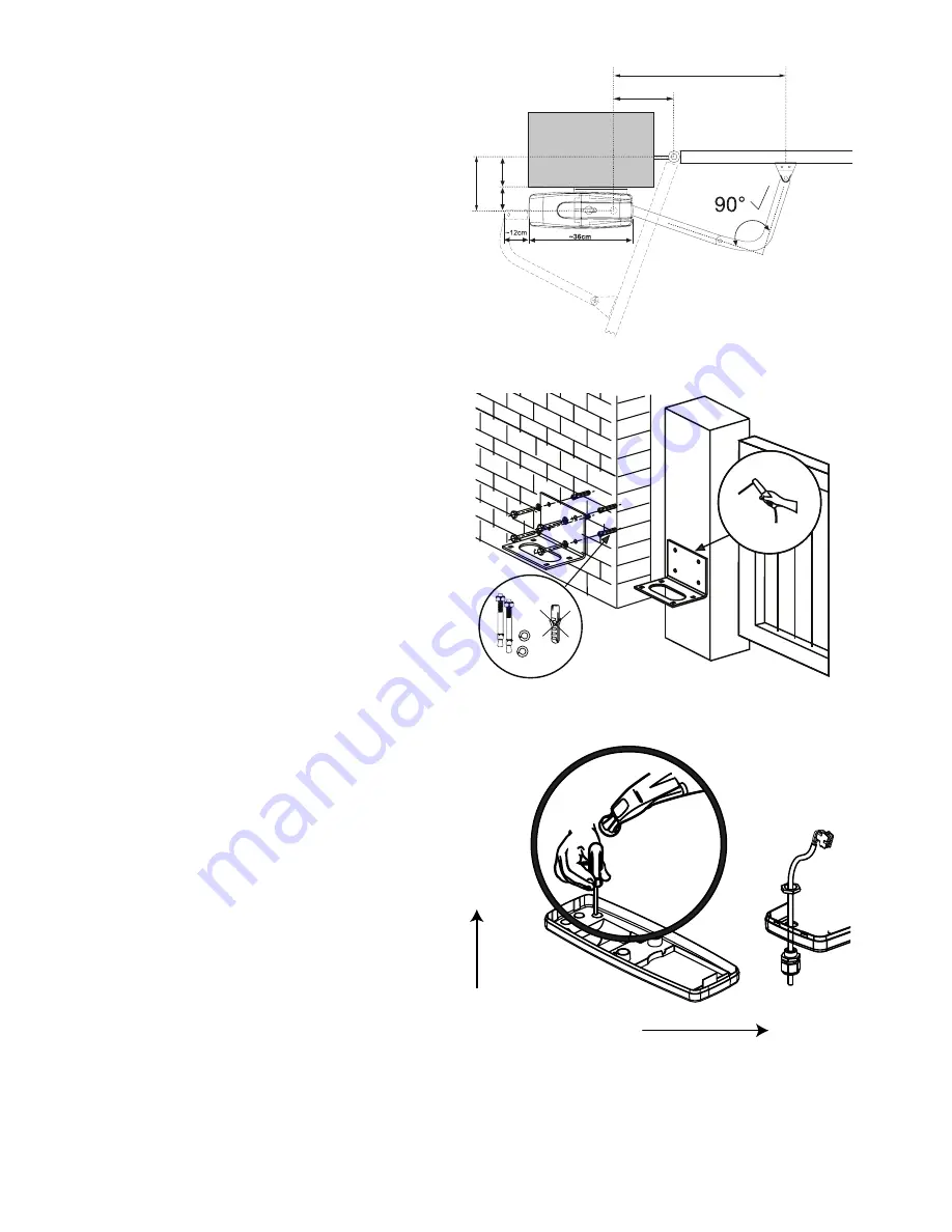
The gate drive mechanism is suitable for use in conjunction
with pillars with a max. thickness of 30cm. The amount of
room around the pier affects the opening angle and the po-
sition of the arms. The drive mechanism is equipped with
built-in limit stops for both the OPEN and CLOSE direc-
tions. A different opening angle can be set for the left-hand
wing as compared with the right-hand one
.
A
=3
8,
5c
m
8,
5c
m
30
cm
C
B=60-70cm
7-8 cm = 90°
max. 10 cm
=
INSTALLATION
Step 1 Install Motor Bracket
For Stone or reinforce concrete pillars use Dynabolts or
Chemical anchors (not supplied) to mount the motor sup-
port bracket onto the wall at the desired height. The gate
motor exerts a considerable force, ensure the wall is suit-
able. It may be necessary to use metal reinforcing, if so
weld the bracket onto the brace to prevent damage to the
wall and or motor.
If fastening to brickwork CHEMICAL ANCHORS should
be used and metal reinforcing is highly recomended.
DO NOT USE PLASTIC ANCHOR TO MOUNT THE
BRACKET IN PLACE.
Step 2 Prepare the Motor Housing
Taking note of the the Motorʼs orientation, carefully knock
out one of the four tap in the base housing as illustrated to
allow for cable entry. Several openings for the cable have
been pre-punched in the base and need only be broken
through. Place the base plate onto a solid surface whilst
breaking the holes through to prevent the PVC base plate
from breaking. A small, flat screwdriver should be used for
breaking the holes through. For this purpose, tap on the
screwdriver handle with the palm of the hand from the in-
side. Repeat this as necessary at several points on the pre-
marked circle. The pre-punched area can then be easily
removed and the strain relief supplied as standard fitted in
its place.
Thread the Terminated Loom through the gland nut and into
the hole knocked out for cable entry. Thread the gland over
the cable and through the knockout hole as illustrated. Fas-
ten the Gland in place firmly with the nut. Hand tighten the
bottom nut, allowing around 200mm of cable to protrude.
Knock out
PILLAR SIDE
Gate
Wall or
Pillar
Summary of Contents for MGA600
Page 15: ...14 Transformer...
Page 20: ...19...
Page 21: ...20 left right NOTES...
Page 22: ...21 TIMER TO CLOSE T b w r t p TTC OFF MAXIMUM time 180 seconds...
Page 23: ...22 C840...
Page 25: ...24 CAUTION 240 VAC Transformer...
Page 27: ...26...
Page 28: ...27...
Page 29: ...28...


