14
WIRING
ELECTRICAL SAFETY
13
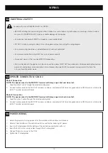
To reduce the risk of SEVERE INJURY or DEATH:
• BEFORE installing the power wiring or control stations be sure to follow all specifications and warnings. Failure to do so
may result in SEVERE INJURY to persons and/or damage to the opener.
• ALL electrical connections MUST be made by a licensed electrician.
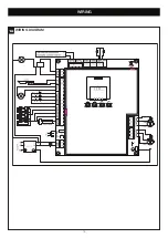
• DO NOT install any wiring or attempt to run the opener without consulting the wiring diagram.
• ALL power wiring should be on a dedicated circuit and well protected.
• ALL power and control wiring MUST be run in separate conduit.
• Disconnect power at the fuse box BEFORE proceeding.
• ANY maintenance to the opener or in the area near the opener MUST NOT be performed until disconnecting the electrical
power (AC and battery). Upon completion of maintenance the area MUST be cleared and secured, at that time the
unit may be returned to service.
Motor1 Connection
NOTE: The opener wired to the MOTOR 1 terminal will always open first and close last.
1. Feed the motor1 cable through the selected cable gland.
2. Connect motor cables to the MOTOR1 terminals as follows: red cable to RED terminal, green cable to GRN terminal , white cable
to WHT terminal on control board.
Motor 2 Connection
NOTE: The opener wired to the MOTOR 2 terminal will always open last and close first.
1. Feed the motor 2 cable through the selected cable gland.
2. Connect motor cables to the MOTOR2 terminals as follows: red cable to RED terminal, green cable to GRN terminal , white cable
to WHT terminal on control board.
OPENER CONNECTION 1 AND 2
14
1. Isolate the power by turning power off at the isolation switch and/or circuit breaker.
2. Select a hole in bottom of the control box to be used for the incoming AC power.
3. Insert an IP rated gland into the bottom of the control box and tighten with nut.
4. Insert the 240V mains supply cables through the IP rated gland.
5. Connect the mains supply to the PCB.
6. Tighten the IP rated gland.
POWER WIRING
15
Summary of Contents for MGLDK
Page 43: ...43 NOTES...


