background image

26

Input Voltage.....

230-240 VAC, 50 Hz

Max. Pull Force

800 N

Rated Load .......

8 Nm

Standby Power .

<1 W

Max. Door Mass..

130 kg

Max.Door Lift Under
Spring Tension....

15 kg

Max. Door Area..

18.0 m

2

Motor

Type ..................

DC gearmotor permanent

lubrication

Drive Mechanism

Drive .................

Belt with two-piece trolley on

steel rail.

Length of Travel

Adjustable to 3 m

Travel Rate .......

127-178 mm per second

Lamp.................

On when door starts, off 2-1/2

minutes after stop.

Door Linkage ....

Adjustable door arm. Pull cord
trolley release.

Safety

Personal ...........

Push button stop in

UP

and

DOWN

direction. Automatic

safety reverse and stop in UP
and reverse in DOWN
direction.

Electronic ..........

Automatic force adjustment

Electrical ...........

Transformer overload protector
and low voltage push button
wiring.

Limit Device ......

Optical RPM/Passpoint

detector.
Limit Adjustment

Electronic, Semi and Fully
Automatic.

Start Circuit.......

Low voltage push button circuit.

Dimensions

Length (Overall)

3.2 m for standard 2.3 m rail

Headroom Required

30 mm

Hanging Weight

14.5 kg

Receiver

Memory Registers

64

Operating Frequency

433.30/433.92/434.54 MHz

SPECIAL NOTE: Chamberlain strongly recommends

that The Protector System

TM

(IR Beams) be installed

on all garage door openers.

SPECIFICATIONS

MAINTENANCE SCHEDULE

Once a Month

• Manually operate door. If it is unbalanced or binding,

call a qualified door technician.

• Check to be sure door opens & closes fully. Adjust

limits and/or force if necessary, refer page 18.

• Repeat the safety reverse test. Make any necessary

adjustments..

Once a Year

• Lightly grease the belt, belt pulley and inside the rail

assembly where the trolley slides.

• Internally the opener does not require additional

lubrication.

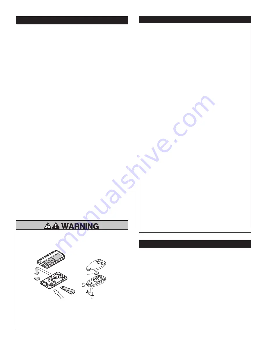
To prevent possible SERIOUS INJURY or DEATH:

• NEVER allow small children near batteries.

• If battery is swallowed, immediately notify doctor.

or

Carefully
Remove Battery
(CR2032 x 1)

THE REMOTE CONTROL BATTERY

To replace battery, use a screwdriver
blade to pry open the case as shown.
Insert battery positive side up.

Dispose of old battery properly.

Your opener can be activated by any of the following devices:
• Open control panel: Up and Down Buttons.
• The Outside Keyswitch or Keyless Entry System (if you

have installed either of these accessories).

• The Remote Control Transmitter. Hold the push button

down until the door starts to move.

Opening the Door Manually: Door should be fully closed if
possible. Weak or broken springs could allow an open
door to fall rapidly. Property damage or serious personal
injury could result.
The door can be opened manually by pulling the release
handle down. To reconnect the door, pull the release handle
down and toward the opener.
Do not use the manual release handle to pull the door
open or closed. When the Opener is Activated by Remote
Control:
1. If open, the door will close. If closed, the door will open.
2. If closing, the door will stop.
3. If opening, the door will stop (allowing space for entry and

exit of pets and for fresh air).

4. If the door has been stopped in a partially open or closed

position, it will reverse direction.

5. If an obstruction is encountered while closing, the door will

reverse.

6. If an obstruction is encountered while opening, the door will

reverse and stop.

7. The optional Protector System™ uses an invisible beam

which, when broken by an obstruction, causes a closing
door to open and prevents an open door from closing. It is
STRONGLY RECOMMENDED for homeowners with young
children.

The opener lights will turn on under the following conditions:
when the opener is initially plugged in; when power is restored
after interruption; when the opener is activated or when the IR
Beams are triggered with the door in the Open position.
They will turn off automatically after 2-1/2 minutes or provide
constant light when the Light feature on the LCD Motion
Detecting Control is activated. Bulb size is E27. Bulb power is
40 watts maximum.

USING YOUR GARAGE DOOR OPENER

CARE OF YOUR OPENER

Summary of Contents for MT3850EVO

Page 1: ...TING INSTRUCTIONS Owner s Copy Keep these Instructions for Future Reference Please read this manual and the enclosed safety materials carefully Periodic checks of the opener are required to ensure saf...

Page 2: ...0...

Page 3: ...your garage has no service entrance door a CM1702 outside quick release must be installed This accessory allows manual operation of the garage door from outside in the event of power failure Keep gar...

Page 4: ...Before you begin Disable locks Remove any ropes connected to garage door Complete the following test to make sure your garage door is balanced and is not sticking or binding 1 Lift the door about hal...

Page 5: ...Door Wall mounted Door Control Opener Vertical Centreline of Door 3 SECTIONAL DOOR INSTALLATION Planning Identify the type and height of your garage door Survey your garage area to see if any of the...

Page 6: ...less Keypad x 2 Merlin Security 2 0 E128M 2 Button Wireless Wall Control Opener Carton Belt Pack Inner Trolley Rail Braces One Piece Rail Header Sleeve Assembly Rail Cartons Max 40Watt E27 Light Bulb...

Page 7: ...omplete ASSEMBLY STEP 2 Install the Belt Remove belt from carton and lay it out on the floor be careful not to allow the belt to twist Hook the trolley connector into the connector slot on the inner t...

Page 8: ...mbly DOOR ASSEMBLY STEP 6 Attach the Rail to the Opener Holding belt out of the way Slide the rail assembly onto shim bracket until rail assembly is securely fastened to the opener Wrap the belt aroun...

Page 9: ...t may slip off pulley if belt is too loose If belt does slip re tighten spring nut by turning nut clockwise a half turn Do NOT over tighten belt Hex Screws Belt Pulley Cover Mounting Plate Opener Belt...

Page 10: ...st point of your door is less than recommended use the maximum height possible as long as the door does not contact the rail or refer to page 9 for ceiling installation To prevent possible SERIOUS INJ...

Page 11: ...eader bracket with coach bolts Ceiling mount Extend vertical centre line onto the ceiling Centre the header bracket on the vertical mark no more than 150 mm 6 from the wall Make sure the arrow is poin...

Page 12: ...base NOTE If the door spring is in the way you ll need help Have someone hold the opener securely on a temporary support to allow the rail to clear the spring Position the rail bracket against the hea...

Page 13: ...the trolley when you raise the door pull down on the trolley arm to disengage the opener Leave the trolley in this position until opener is fastened in place NOTE Timber spacers should be left in plac...

Page 14: ...ake sure the rail is centred over the door or in line with the header bracket if the bracket is not centred above the door 7 Remove timber spacer Operate the door manually If the door hits the rail ra...

Page 15: ...t using the two self threading screws Figure 2A Alternately use two 8 mm bolts spring washers and nuts not provided Figure 2B Metal insulated or lightweight factory reinforced doors Drill 4 5 mm faste...

Page 16: ...gether Find two pairs of holes that line up and join sections Select holes as far apart as possible to increase door arm rigidity Figure 3 If holes in curved arm are above holes in straight arm discon...

Page 17: ...edly NEVER use emergency release handle unless garage doorway is clear of persons and obstructions NEVER use handle to pull door open or closed Lens Hinge 40 Watt Max Standard Light Bulb Release Tab I...

Page 18: ...ng on battery power A flashing orange LED with beep indicates the opener is operating on battery power and that the battery charge is low To test the battery is functioning properly open and close the...

Page 19: ...n the door travels to the programmed UP limit the DOWN Arrow Button will begin to flash 7 Press and release the DOWN Arrow Button to test the DOWN limit The door will travel to the programmed DOWN lim...

Page 20: ...4 complete travel cycles to test adjustment If the opener continues to fail the Safety Reverse Test call for a qualified door technician IMPORTANT SAFETY CHECK Test the Safety Reverse System once a mo...

Page 21: ...with wall plugs and screws provided Ensure they do not obstruct the door movement Wiring Process Align the Sensors to face each other and tighten if necessary The wiring should exit from the bottom of...

Page 22: ...TO CLOSE FEATURE TTC OFF 1 long flash 1 min 1 short flash 5 min 2 short flashes 10 min 3 short flashes UP Arrow Button Learn Limits Button DOWN Arrow Button Battery Status LED Learn Button LED Figure...

Page 23: ...your opener using the steps below NOTE If adding an installed wall control E138M you will need a second person to press and hold the desired button If not installed program the wall button into the op...

Page 24: ...tification number PIN of your choice 4 Press and release the ENTER button Check to see if the bulb blinks If not slowly press and release the ENTER button until the light bulb blinks To change an exis...

Page 25: ...frozen to ground Remove any obstruction The garage door spring may be broken Have it replaced Check battery LED for status refer page 16 2 Door operates from door control but not from remote Replace...

Page 26: ...Wall mounted door control The wires for the door control Check the door control wiring is will not function are shorted or the door correct control is faulty 1 4 1 FLASH 4 FLASHES The garage door open...

Page 27: ...odule Reset limits force contact service centre 4 6 4 FLASHES 6 FLASHES The door reverses for no apparent The Protector System was Remove obstruction or realign reason while travelling down temporaril...

Page 28: ...Y To replace battery use a screwdriver blade to pry open the case as shown Insert battery positive side up Dispose of old battery properly Your opener can be activated by any of the following devices...

Page 29: ...ation for Service Personnel If the supply cord is damaged it must be replaced by the manufacturer its service agent or similarly qualified persons in order to avoid hazard NOTE Only genuine Merlin acc...

Page 30: ...lley 183D0177 Segmented rail sections 183D0178 Segmented rail braces 012C0855 Header bracket 171A0028 031D0537 Belt pulley cover Replacement belt packs 041A5844 2 3m 041A5844 1 2 5m 041A5844 2 3 0m 84...

Page 31: ...res Chamberlain or its Professional Dealer will provide you with either repairs to the Unit or a replacement Unit Repairs and replacement parts provided under this Chamberlain Limited Warranty are pro...

Page 32: ...nc TM TrademarkofTheChamberlainGroup Inc RegisteredTrademarkofTheChamberlainGroup Inc Warranty Registration To validate your warranty you must complete the registration form online at gomerlin com au...

Reviews: