background image


2 - MACHINE TECHNICAL INFORMATION 


2 - 28 


SERIAL NUMBER OF THE MACHINE 
   
CHASSIS NUMBER 
 
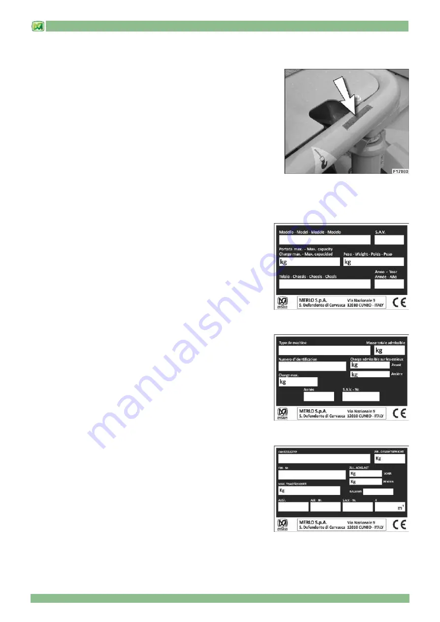
The  chassis  number  of  your  machine  is  printed  on  the  front  right  side  of  the 
chassis,  and  coated  with  a  layer  of  black  paint.  When  requesting  assistance  or 
spare  parts,  please  provide  Merlo  Technical  Support  Service  with  both  the 
chassis number and the Sav number of your machine. 
This  code  is  made  up  of  17  characters,  divided  into  3  sectors,  and  shows  the 
manufacturing data of your machine. 
An example of a chassis number stamped on a chassis is given below:  
 
• chassis identification code: ZF1A28L01C1190883 
 
ZF1: code that identifies MERLO S.p.A. 
A28L01: specific model code 
C1190883:  code  that  identifies  the  manufacturing  decade  (C=  2010-2019),  the  manufacturing  year  (1=2011),  the 
manufacturing progressive number (1908), and the engine code (83) 
 
 
IDENTIFICATION AND TYPE APPROVAL PLATES 
 
• MACHINE IDENTIFICATION PLATE 
 
The  machine  identification  plate  is  placed  in  the  rear  left  part  of  the  cab  and 
provides the operator with the following data: 
 
- Model 
- SAV number 
- Maximum capacity 
- Weight 
- Chassis number 
- Manufacturing year 


• MACHINE IDENTIFICATION PLATE (SWISS MARKET) 
 
The  machine  identification  plate  is  placed  in  the  rear  left  part  of  the  cab  and 
provides the operator with the following data: 
 
- Model 
- Total permissible mass 
- Chassis number 
- Maximum permissible load per axle (front and rear) 
- Maximum load 
- Manufacturing year 
- SAV number 


• MACHINE IDENTIFICATION PLATE (GERMAN MARKET) 
 
The  machine's  identification  plate  is  applied  in  the  engine  compartment  and 
provides the operator with the following information: 
 
- German homologation certificate (ABE) 
- Total weight of the machine 
- Chassis number 
- Weight on front and rear axle 
- Capacity of the machine 
- Manufacturing year 
- ABE version 
- ABE homologation number 
- SAV number of the machine 
- Total unladen mass of the machine 


Summary of Contents for PANORAMIC

Page 1: ...Tel 39 0171614111 Fax 39 0171614100 www merlo com info merlo com PANORAMIC 02 GB VALID FROM SAV C422222 USER AND MAINTENANCE MANUAL VARIABLE REACH TRUCK TRANSLATION OF THE ORIGINAL INSTRUCTIONS...

Page 2: ...N 2 STICKERS WITH CONTROL DESCRIPTIONS LEAFLETS IN THE CAB 3 CONTROLS AND INSTRUMENTS 4 OPERATING INSTRUCTIONS 5 ORDINARY MAINTENANCE 6 PERIODICAL SAFETY CONTROLS 7 ATTACHMENTS AND OPTIONAL EXTRA 8 HY...

Page 3: ...FIRST COMMISSIONING OR RECOMMISSIONING AFTER A LONG SHUTDOWN 3 MACHINE GARAGING 4 TYRES 4 ORIGINAL MERLO SPARES 4 MACHINE SCRAPPING 4 WARRANTY 5 ORDINARY MAINTENANCE OPERATIONS 5 INFORMATION FOR DRIV...

Page 4: ...cations for use storage and maintenance are also fundamental for the intended use of this machine This machine must only be used by qualified skilled and authorized personnel Operators must be familia...

Page 5: ...machine when the workplace does not have external fire extinguishing equipment and the risk of fires exists The machine is supplied with a leaflet stating the maximum permissible wind under normal ope...

Page 6: ...ARNING The list of tyres that are authorized and installed on your machine are shown in the paragraph PERFORMANCE AND FEATURES of chapter TECHNICAL INFORMATION In the event a type of tire needs to be...

Page 7: ...to regularly carry out all ordinary maintenance operations following closely the instructions provided by the present operator manual Do not use the machine unless all maintenance operations and any n...

Page 8: ...ry time before use if you stop your machine on sloping ground place wheel chocks if present under its wheels avoid operating the machine on a muddy sandy or soft ground never use the controls or the p...

Page 9: ...achine since they may damage it or injure the operator periodically inspect the wear level of hydraulic hoses if they are worn replace them FIRE PREVENTION MEASURES Follow the instructions below make...

Page 10: ...y are all labelled with the specific CE marking NOISE AIRBORNE NOISE This machine complies with Directive 2000 14 CE Legislative Decree n 262 dated 04 October 2002 concerning acoustic emissions in to...

Page 11: ...ws LIFTING a 0 18 MINIMUM b 0 58 TRACTION c 0 24 References a b c are coefficients proportional to usage time During equipment operation higher noise levels may be measured due to particular working c...

Page 12: ...S P37 12 PLUS 16 DIMENSIONS P38 12 PLUS P38 12 16 DIMENSIONS P38 13 PLUS P38 13 P38 13EE 17 DIMENSIONS P38 14 PLUS P38 14 17 DIMENSIONS P40 9 PLUS 18 DIMENSIONS P40 17 PLUS P40 17 P40 17EE 18 DIMENSIO...

Page 13: ...12 PLUS P40 9 PLUS REF DESCRIPTION REF DESCRIPTION 1 Operator cab 9 Fork tilt jack 2 Engine compartment and battery compartment 10 Crossways tilt correction jacks 3 Front axle brake callipers wheel re...

Page 14: ...partment and battery compartment 10 Crossways angle correction jacks 3 Front axle brake callipers wheel reducers 11 First boom 4 Rear axle brake callipers parking brake calliper wheel reducers 12 Seco...

Page 15: ...attery compartment 10 Crossways angle correction jacks 3 Front axle brake callipers wheel reducers 11 First boom 4 Rear axle brake callipers parking brake calliper wheel reducers 12 Second boom 5 Fork...

Page 16: ...Fork tilt jack 3 Electronic control unit compartment 12 Crossways angle correction jacks 4 Rear axle brake callipers wheel reducers 13 First boom 5 Front axle brake callipers parking brake calliper w...

Page 17: ...ing jacks 2 Engine compartment and battery compartment 9 Fork tilt jack 3 Front axle brake callipers wheel reducers 10 Crossways angle correction jacks 4 Rear axle brake callipers parking brake callip...

Page 18: ...2 MACHINE TECHNICAL INFORMATION 2 7 CAB INTERIOR KEY WORD only for models P37 12PLUS P38 12PLUS P38 13PLUS P38 14PLUS P40 9PLUS P40 17PLUS P60 10 P72 10...

Page 19: ...fety instruction holder 22 Steering wheel 24 Parking lights switch low beam lights Direction indicators head lights Horn 26 Lever for the selection of the air suction from inside outside the cab 27 Dr...

Page 20: ...2 MACHINE TECHNICAL INFORMATION 2 9 only for models P60 10EE P72 10EE...

Page 21: ...ent 19 Gear control 20 Drive direction selector 21 Load chart and safety instruction holder 22 Steering wheel 24 Parking lights switch low beam lights Direction indicators head lights Horn 26 Lever fo...

Page 22: ...2 MACHINE TECHNICAL INFORMATION 2 11 only for models P38 12 P38 13 P38 14 P40 17 P38 13EE P40 17EE...

Page 23: ...lever 18 Air vent 19 Gear control 20 Drive direction selector 21 Load chart and safety instruction holder 22 Steering wheel 24 Parking lights switch low beam lights Direction indicators head lights Ho...

Page 24: ...amp 6 Operating mode selector switch 8 Starter key 9 Emergency lights 11 Portable lamp socket 37 Parking brake selector 43 Lifting equipment load limiting device 61 Side tilt corrector control 204 The...

Page 25: ...flashing light switch 35 Heating cock 36 Fan switch for cab heating 226 Adjustment buttons for instrument panel settings C INSTRUMENT PANEL C DESCRIPTION REF DESCRIPTION 58 Coolant thermometer 59 Fuel...

Page 26: ...LOAD CONTROL DISPLAY D only for models P37 12PLUS P38 12PLUS P38 13PLUS P38 14PLUS P40 9PLUS P40 17PLUS P60 10 P72 10 REF DESCRIPTION 210 Light bar indicating percentage machine stability S1 Machine o...

Page 27: ...2 MACHINE TECHNICAL INFORMATION 2 16 DIMENSIONS P37 12 PLUS DIMENSIONS P38 12 PLUS P38 12...

Page 28: ...2 MACHINE TECHNICAL INFORMATION 2 17 DIMENSIONS P38 13 PLUS P38 13 P38 13EE DIMENSIONS P38 14 PLUS P38 14...

Page 29: ...2 MACHINE TECHNICAL INFORMATION 2 18 DIMENSIONS P40 9 PLUS DIMENSIONS P40 17 PLUS P40 17 P40 17EE...

Page 30: ...2 MACHINE TECHNICAL INFORMATION 2 19 DIMENSIONS P60 10 P60 10EE DIMENSIONS P72 10 P72 10EE...

Page 31: ...P40 17 P40 17EE 10350 kg P60 10 P60 10EE 9800 kg P72 10 P72 10EE 10650 kg PERFORMANCE Machine Maximum capacity kg Lift height mm Maximum reach mm Speed Km h 1st gear 2nd gear P37 12 PLUS 3700 11560 7...

Page 32: ...missions EURO3 phase IIIA Tier 3 ENGINE P38 13EE P40 17EE P60 10EE P72 10EE KUBOTA V3800 DI T Turbo Diesel water cooled Power 74 kW 100CV at 2600 rpm Reduced emissions EURO3 phase IIIA Tier 3 HYDRAULI...

Page 33: ...has been approved by Merlo refer to the file of diagrams shown at the back of this manual DO NOT use any attachment if the corresponding load chart diagrams file inside the cab and at the back of this...

Page 34: ...2 MACHINE TECHNICAL INFORMATION 2 23 MACHINE WITH STABILISERS LIFTING A LOAD USE CONDITIONS TRANSPORTING A LOAD...

Page 35: ...2 MACHINE TECHNICAL INFORMATION 2 24 LIFTING A LOAD...

Page 36: ...the load symmetrically centred Secure the oscillating load 5 Indications of machine at a standstill a on stabilisers b on tyres WARNING The load charts for the machine on tyres refers to a machine tha...

Page 37: ...AND FEATURES of chapter TECHNICAL SPECIFICATIONS In the event a type of tire needs to be replaced with another model in the list of those authorized contact the Merlo Technical Assistance Service sin...

Page 38: ...f the machine 19 Position of load transportation a Maximum transportable capacity b Load transport height from the ground c Telescopic boom completely retracted d Carriage rotation carriage rotated co...

Page 39: ...ode 83 IDENTIFICATION AND TYPE APPROVAL PLATES MACHINE IDENTIFICATION PLATE The machine identification plate is placed in the rear left part of the cab and provides the operator with the following dat...

Page 40: ...driving on public roads is located in the front part of the cab and provides the operator with the following data A Type of machine B Modification C Manufacturing year D Identification no E Type appr...

Page 41: ...6 1 0 62 8 9 0 91 10 4 1 06 M6 x 1 10 4 1 06 15 3 1 56 17 9 1 82 M7 x 1 17 2 1 75 25 2 55 30 3 06 M8 x 1 25 25 2 55 37 3 77 44 4 49 M10 x 1 5 50 5 10 73 7 44 86 8 77 M12 x 1 75 86 8 77 127 12 95 148...

Page 42: ...3 STICKERS WITH CONTROL DESCRIPTIONS LEAFLETS IN THE CAB 3 1 CONTENTS GENERAL REMARKS 2 INSIDE CAB STICKERS 2 OUTSIDE CAB STICKERS 7 END OF SECTION 14...

Page 43: ...ed or illegible replace them with new original ones to be ordered from Merlo Technical Support Service and to be placed in the positions shown in the Operator s Manual Most of the symbols used are bas...

Page 44: ...3 STICKERS WITH CONTROL DESCRIPTIONS LEAFLETS IN THE CAB 3 3 only for models P60 10EE P72 10EE...

Page 45: ...3 STICKERS WITH CONTROL DESCRIPTIONS LEAFLETS IN THE CAB 3 4 only for models P38 13 P38 13 P38 14 P40 17 P38 13EE P40 17EE...

Page 46: ...3 STICKERS WITH CONTROL DESCRIPTIONS LEAFLETS IN THE CAB 3 5 CONTROL PANEL STICKERS P only for models P37 12PLUS P38 12PLUS P38 13PLUS P38 14PLUS P40 9PLUS P40 17PLUS P60 10 P72 10...

Page 47: ...3 STICKERS WITH CONTROL DESCRIPTIONS LEAFLETS IN THE CAB 3 6 only for models P38 12 P38 13 P38 14 P40 17 P38 13EE P40 17EE P60 10EE P72 10EE...

Page 48: ...3 STICKERS WITH CONTROL DESCRIPTIONS LEAFLETS IN THE CAB 3 7 OUTSIDE CAB STICKERS P40 17 PLUS P40 17 P40 17EE...

Page 49: ...3 STICKERS WITH CONTROL DESCRIPTIONS LEAFLETS IN THE CAB 3 8...

Page 50: ...3 STICKERS WITH CONTROL DESCRIPTIONS LEAFLETS IN THE CAB 3 9 P38 12 PLUS P38 13 PLUS P38 12 P38 13 P38 13EE P38 14 P38 14PLUS...

Page 51: ...3 STICKERS WITH CONTROL DESCRIPTIONS LEAFLETS IN THE CAB 3 10...

Page 52: ...3 STICKERS WITH CONTROL DESCRIPTIONS LEAFLETS IN THE CAB 3 11 P37 12 PLUS P40 9 PLUS...

Page 53: ...3 STICKERS WITH CONTROL DESCRIPTIONS LEAFLETS IN THE CAB 3 12...

Page 54: ...3 STICKERS WITH CONTROL DESCRIPTIONS LEAFLETS IN THE CAB 3 13 P60 10 P72 10 P60 10EE P72 10EE...

Page 55: ...3 STICKERS WITH CONTROL DESCRIPTIONS LEAFLETS IN THE CAB 3 14 END OF SECTION...

Page 56: ...SYSTEM M CDC 16 FRONT ANTI TIP OVER CONTROL 27 JOYSTICK 1 27 MAIN DISTRIBUTOR LEVER 1 2 28 HYDRAULIC OR HYDROSTATIC SYSTEM PRESSURE GAUGE 12 29 PEDALS 14 15 27 29 LEVER FOR THE ADJUSTMENT OF THE STEE...

Page 57: ...rasping the handrail D and pulling firmly inwards fig 3 ATTENTION The lower part of the driver s cab must always be closed both during transfers with the machine and when working OPENING THE CAB DOOR...

Page 58: ...tside of the cab release stop B1 by acting on its tongue C1 fig 8 completely close the upper part of the door and lock it into position by rotating handle A downwards in the direction shown by the arr...

Page 59: ...ever A to the left then open the window pushing it forward to the desired position REAR WINDOW CLOSING Rotate the lever A to the right to the automatic stop position CAB LIGHT The cab courtesy light P...

Page 60: ...s weight direction R to tighten the suspension direction S to slacken the suspension BACK ADJUSTMENT 4 Sit with your back firmly against the seat back Lift lever L upwards to position the back to the...

Page 61: ...ature of the engine coolant at regular intervals If the temperature reaches the upper limit indicated by a red line and the yellow indicator light ON you must switch off the engine immediately and wai...

Page 62: ...ng Crab steering engaged pay special attention during movements 56 Chassis side shift Shift system not in central position 57 Parking brake Activation of the parking brake with the direction selector...

Page 63: ...the number of hours the machine has been used since the last reset The maximum value that can be displayed is 999 99 hours and then it starts again from 0 0 To reset the partial hour counter press th...

Page 64: ...m air temperature not active on this model Steady No Hydrostatic transmission oil temperature Function corresponding to warning light 49 Steady No Hydrostatic transmission oil level Function correspon...

Page 65: ...the central position neutral and then engage the required gear To drive the machine the operator must sit correctly in the driver s seat indicator light 90 OFF Shift the drive direction selector to th...

Page 66: ...cidental control operation whilst driving the machine on the road When this operating mode is selected the system switches off the display D in the cab C Emergency movements command with spring return...

Page 67: ...GHT 11 The indicated socket 11 can be used to feed a portable light equipped with a normal electric cigarette lighter connection Use a 12 V and max 40 W lamp PARKING BRAKE 37 With engine running Turn...

Page 68: ...dynamic load chart Fig 4 In this case the operator must perform the movements that do not worsen the overload on the attachment as they are required to restore safe working conditions indicator light...

Page 69: ...43 on the control panel Fig 3 the acoustic alarm in the cab In this case the operator must perform the movements not aggravating the overload of the attachment needed to restore the safe operating con...

Page 70: ...ys tilt corrector is prevented by a specific device DESCRIPTION OF THE COMMAND PANEL P1 HEATING 35 COCK REF 35 A maximum temperature C minimum temperature CAB FAN SWITCH REF 36 0 fan OFF 1 fan activat...

Page 71: ...following steps before leaving the driving cab place the gear selector 19 in the neutral position N place the direction selector 20 in neutral position N engage the parking brake 37 switch off the mac...

Page 72: ...from external limit of tyres or stabilisers if present in metres 216 Telescopic boom lifting angle in degrees 219 Colour indicator green yellow red of the position of the lifted load on the carriage...

Page 73: ...on buttons are P1 press button P1 to activate the display set up menu D where day night brightness and speaker volume can be adjusted P2 press button P2 to activate the telecamera installed on the mac...

Page 74: ...s button P4 to switch between day and night brightness mode for the display D The system signals the operator that the setting has been made by showing window 1 day mode or 2 night mode in the middle...

Page 75: ...der these conditions the indicative load readout tolerance is about 5 of maximum rated load The weight of the lifted load is merely indicative for the operator and has no fiscal and or certified weigh...

Page 76: ...the weighing screen Fig 2 5 WEIGHING MODE F This command is used to set the weighing readout mode 1 MANUAL 2 AUTOMATIC If manual weighing is set the symbol X and the item MAN WEIGHING appears if auto...

Page 77: ...acity chart for the machine attachment set up The 4 positions of the selector switch 204 for the type of attachment installed on the carriage are Fig 1 a AUTO auto identification of the attachment ins...

Page 78: ...the symbol in field 222 of the display D in the cab Fig 5 For a better understanding of the attachment auto identification and manual selection system a table is provided with all the icons used in fi...

Page 79: ...to attachments whose centre of gravity is no more than 1 5 metres ahead of the carriage The attachment installed on your machine is either not equipped with a self identification sensor or it was not...

Page 80: ...as correctly identified by the system The FLY JIB FLY JIB WITH WINCH attachment installed on the machine was correctly identified by the system Attachments whose centre of load gravity is 4 metres fro...

Page 81: ...cabin The sound becomes more frequent as it reaches 100 red zone over 100 Fig 3 longitudinal stability limit reached with consequent block of movements that may worsen the condition instrument panel...

Page 82: ...copic boom Position F retract telescopic boom Position G release attachments installed on carriage Position H command for attachments installed on carriage Button L shift machine to right Button M shi...

Page 83: ...ght 56 off CONTROL LEVERS ENABLING BUTTONS U1 AND U2 U1 Press and hold the button U1 to enable the controls of the lever 1 U2 Press and hold the button U2 to enable the controls of the lever 2 LEVER 1...

Page 84: ...hicle down independently of the diesel engine rpm and in any working condition it can be used continuously without causing damage or wear to the transmission It is particularly useful to approach a lo...

Page 85: ...with machine at a standstill When reverse gear is selected the reverse alarm system will be activated automatically and an intermittent audible warning signal will sound When the machine is moving the...

Page 86: ...witch of control lever 24 to position 0 TAIL LIGHTS Fig N To switch on the tail lights turn the switch of control lever 24 to position 1 LOW BEAM HEADLIGHTS Fig P To switch on the low beam lights turn...

Page 87: ...and all wheels are aligned with the chassis The correction of a possible misalignment between the front and the rear wheel can be achieved by bringing the steering wheel to its end stop for a few sec...

Page 88: ...load chart so as to prevent the machine stability control system to step in with a consequent block of all controls It is possible to lift loads on an uneven ground by correctly stabilising the machin...

Page 89: ...S FOR LOAD TRANSPORT 3 MACHINE OPERATING AREA 3 HOW TO HANDLE A LOAD 4 INSTRUCTIONS FOR STARTING YOUR MACHINE 6 INSTRUCTIONS FOR DRIVING YOUR MACHINE ON THE ROAD 11 INSTRUCTIONS FOR THE CORRECT USE OF...

Page 90: ...owing forks are supplied as standard Fork type A0301 Standard fork Weight of a single fork 85 kg Rated load capacity 2250 kg Centre of gravity of the load P from the fork heel 500 mm Machines P60 10 P...

Page 91: ...t be lifted to about 0 5 metres from the ground while driving your machine from one spot to another avoid sharp acceleration and braking while driving your machine from one spot to another always keep...

Page 92: ...load and lift it a few centimetres Fig 6 rotate the carriage a few degrees upwards and completely retract the telescopic boom Fig 7 MANOEUVRING A CIRCULAR SHAPED LOAD For handling circular shaped loa...

Page 93: ...ad chart present in the holder provided in the cab If operations with the platform must be carried out near overhead electricity cables the person in charge must ask whoever manages the cables and the...

Page 94: ...nd turn on the rotating signal lamp on top of the cab never transport passengers in the cab and on no other part of the vehicle always respect the rules in force in the country where you are driving n...

Page 95: ...o screws or bolts are loose or missing and that there are no leakages of hydraulic oil roof rotating flashing beacon figure 1 water level in the radiator figure 2 hydrostatic transmission oil level fi...

Page 96: ...ion R and carry out the following checks warning light panel figure 7 correct operation of all control switches figure 8 front lights and direction indicators figure 9 rear lights and direction indica...

Page 97: ...rake 37 is engaged the drive direction selector 20 is in neutral position N Then turn the ignition key 8 as follows turn the ignition key 8 to position R to turn on the instrument panel turn the ignit...

Page 98: ...y the parking brake Fully retract the telescopic boom Lower the forks to the ground Let the engine idle for 2 minutes before stopping it Turn the ignition key 8 to position 0 the engine automatically...

Page 99: ...escopic boom make sure that the attachment carriage is perpendicular to the ground the carriage is in the correct position if the red stripe on the carriage is aligned with the one on the boom head se...

Page 100: ...NG THE MACHINE towing of the vehicle must be carried out using the special points prepared for this purpose never use cables belts or chains to tow the machine or to have it towed since they can break...

Page 101: ...ker as described below A Machine lifting points B Machine anchorage points Disassemble the vehicle attachments Assemble suitable clevis in each of the points indicated Lower and retract the vehicle bo...

Page 102: ...you are advised to inquire the minimum safety distance from such lines from the operator of the said lines as well as from the authorities in charge of safety and health in the workplace Please note t...

Page 103: ...AND LUBRICANTS 3 SCHEDULED MAINTENANCE DURING THE MACHINE S RUNNING IN PERIOD 6 COVERS 9 ENGINE COMPARTMENT NOMENCLATURE 11 MERLO PERIODIC MAINTENANCE SCHEDULE 12 EVERY 10 HOURS OR DAILY 14 EVERY 50 H...

Page 104: ...devices must be worn when handling lubricants gloves masks overalls etc In order to avoid personal burns or fires do not work on heated fluids or components INFORMATION ON ORIGINAL MERLO SPARE PARTS...

Page 105: ...iously to relieve any residual pressure stay out of the way during draining operations and always wear protection goggles Slowly unscrew the draining screw by a few turns to let either the condensate...

Page 106: ...vide for their own supply following the above mentioned regulations For control and replacement operations refer to the information in the instruction manual The oils chart is also enclosed as a bookl...

Page 107: ...NS GEAR BOX ESSO GEAR OIL GX 80W 90 MOBILUBE HD 80W 90 SPIRAX HD Q8 T 55 80W 90 SAE 80W 90 MIL L 2105C DIFFERENTIALS REDUCTION HUB CHAIN TRANSFER UNIT GREASES CHART FOR USE OF THE MACHINE IN NORMAL TE...

Page 108: ...electrolyte level in the battery and the proper connection of the and terminals Grease the indicated points see also the table below Check the correct tightening of components at the indicated torque...

Page 109: ...he correct tyre inflation pressure is indicated on the sticker on the inside of the wheel rim Check the correct tightening of the wheel columns B If needed tighten the columns to a torque of 550 Nm SC...

Page 110: ...5Kgm To better understand the position of the V2 screws which fasten the front A and rear P axles to the frame refer to the drawing below SCHEDULED MAINTENANCE AFTER THE FIRST 100 HOURS CARDAN JOINTS...

Page 111: ...he rear part of the machine and contains components of the telescopic boom slide pads lock valve for the extension jack etc To remove COVER 4 unscrew the 3 screws shown in the picture with an appropri...

Page 112: ...proceed as follows fit the cover in its seat push the cover fully into place close the lock using the special key provided COVER 7 The electrical box containing the fuses the relays and the electronic...

Page 113: ...Fuses and relays 14 Gear box oil bleeding small tank 15 Chain transfer unit P38 13EE P40 17EE P60 10EE P72 10EE KUBOTA 74 kW 100CV 1 Diesel engine 2 Hydrostatic transmission oil level small tank 3 Eng...

Page 114: ...000 hours also carry out the maintenance operations foreseen at 500 50 and 10 hour intervals The 5 scheduled maintenance bands indicated in the table below will be described in further detail in the...

Page 115: ...ONENT EVERY 500 HOURS OPERATION Hydraulic oil tank bleeder filter Replace the filter Reduction hub oil Check level Differential oil Check level Gear box oil Check level Cap screws and bolts Check tigh...

Page 116: ...smission oil present in tank A WARNING Do not remove cap B unless the engine is cold Release all pressure before fully removing the cap The hydrostatic oil level must be visible in the indicator glass...

Page 117: ...ract the boom a few times so as to evenly distribute the grease inside the pads ARTICULATED JOINT OF THE WHEEL REDUCTION HUBS To ensure optimum performance of the wheel reduction hubs grease them as f...

Page 118: ...and or in the machine registration document if provided CAB VENTILATION SYSTEM FILTER To check its cartridge follow the instructions below Unscrew fastening screws V Extract the cab ventilation filter...

Page 119: ...e B can be cleaned by following the instructions here below direct a jet of compressed air not over 5 bars from the inner side to the outer side of the cartridge tap the cartridge against your palm ma...

Page 120: ...ks on all the outer sliding pads of each boom 1 visual inspection of outer sliding pads to check for wear 2 visual inspection of outer sliding pads to check for wear uniformity 3 visual inspection of...

Page 121: ...Excess grease inside the chamber is expelled from the side of plunger A during the first cycle EVERY 500 HOURS OR EVERY 6 MONTHS HYDRAULIC SUMP BLEED FILTER Replacement of the filter cartridge Unscre...

Page 122: ...ing 1 see paragraph COVERS Then carry out the following operations Remove cap A Check that the gearbox oil reaches the edge of the hole If necessary top up with the specific oil see OIL TABLE in chapt...

Page 123: ...ion filter place an appropriately sized container underneath filter A loosen filter A use an appropriate chain or belt extractor to carry out this operation collect the oil that flows out remove filte...

Page 124: ...c boom remove rear case 4 first see also paragraph COVERS Perform the following checks on the inner sliding pads of the telescopic boom 1 visual inspection of inner sliding pads to check for wear 2 vi...

Page 125: ...condition and free from obstructions otherwise replace it with a part from the Merlo Technical Assistance service replacing the filter connecting the pipelines and securing the retainer clamps B WARNI...

Page 126: ...Wheel reduction hubs B Front axle C Rear axle D Boom E Carriage F Fork jack G Lifting jack H Offset jack L Stabilisers if fitted to the machine NOTE A P40 17PLUS has been selected to explain this main...

Page 127: ...e same operations for the telescopic boom on your machine 1 or 2 extensions depending on the model AIR VENTILATION FILTER Replace the filter of the cab ventilation system as follows Unscrew fastening...

Page 128: ...reconnect piping F in its correct position install a new filter 5 for the hydrostatic transmission The system must be filed with specific hydraulic oil filtered at 10 micron and supplied at a pressure...

Page 129: ...cap B The total capacity of the system is 105 litres 140 litres for P40 17 P40 17PLUS P40 17EE GEAR BOX OIL To correctly change the gearbox oil do as follows Stop the machine diesel engine open cover...

Page 130: ...well SYSTEM CAPACITY The total capacity of the system is 5 3 litres FRONT AXLE A REAR AXLE P REDUCTION HUB OIL NOMENCLATURE A filler cap B discharge cap C bleeder cap To correctly change the wheel re...

Page 131: ...e loosen the side lock nuts A tighten dowels A fully in the same way on both sides to centre the boom loosen the dowels by 1 2 a turn to give the necessary clearance and tighten the lock nuts To adjus...

Page 132: ...es of the boom and then tighten proceeding in a criss cross manner Loosen by 1 2 turn all the side dowels and tighten the counter nuts remove the bridge crane or in the event a ground blockage was use...

Page 133: ...from the machine s controls to clean the outside of the vehicle and the engine it is advisable to use a pressure washer keeping in mind the following make sure that all filler caps of the radiator of...

Page 134: ...ting the dipstick A the level must be above the minimum mark WARNING Do not start the diesel engine if the oil level is below the minimum mark Do not fill the engine oil tank above the maximum level T...

Page 135: ...A situated inside the cab with the specific liquid available on the market GEAR BOX OIL BLEEDING TANK The gearbox oil breather small tank is located inside the engine compartment and is maintenance f...

Page 136: ...t is slack Adjust belt tension Should you notice any other failures in the electrical equipment please contact Merlo Technical Assistance service BRAKING SYSTEM Excessive brake pad wear Replace brake...

Page 137: ...models with DEUTZ engine Using the EMERGENCY function in the event of an electronic fault with the hydrostatic transmission for example the machine does not move either forwards or backwards it is po...

Page 138: ......

Page 139: ...DES 7 PLATES AND INSTRUCTIONS 7 STABILISERS COMMAND LOCK 7 CROSSWAYS LEVELLING TILTING COMMANDS LOCK 7 USE AND MAINTENANCE INSTRUCTIONS MANUAL 7 POWER STEERING UNIT CALIBRATION PRESSURE 7 HYDRAULIC SY...

Page 140: ...Date Restoration Date Functioning of the anti overturn system acoustic alarm Functioning of the anti overturn system visual alarm Functioning of the anti overturn system movement locking Functioning...

Page 141: ...ntenance instruction manual is in the cab Check spirit level calibration Check the maximum pressure in the oleodynamic system Check the jack locking valves Check the parking brake Check of the three s...

Page 142: ...operating and maintenance instruction manual is in the cab Check spirit level calibration Check the maximum pressure in the oleodynamic system Check the jack locking valves Check the parking brake Che...

Page 143: ...cab Check spirit level calibration Check the maximum pressure in the oleodynamic system Check the jack locking valves Check the parking brake Check of the three steering operating modes Check the powe...

Page 144: ...rear semi axle to the end of its travel 9 Extract the boom until the point where the anti overturn system intervenes sound and visual alarm block of movements 10 Check the length of the boom in refer...

Page 145: ...USE AND MAINTENANCE INSTRUCTIONS MANUAL Make sure the manual is effectively in the cab and in good condition In case of loss or damage request a duplicate indicating if possible the reference code at...

Page 146: ...ntre PARKING BRAKE Start the engine and engage 2nd gear Check that the gear is engaged by driving the machine for a short distance Engage the parking brake Whilst keeping one foot on the brake engage...

Page 147: ...40 17 P40 17PLUS P40 17EE INSPECTION OF CHAINS a chains inside the boom To check the integrity and the state of wear of chains A as well as their correct fitting on combs B extend the telescopic boom...

Page 148: ...eed to adjust the chains as follows The distance between the second and third boom position A is adjusted by using the adjusting screws A that between the third and fourth boom position B is adjusted...

Page 149: ...sure the distance between the chains and the lower surface of the second and third boom sections make the measurement in mid length of the chain Then retract the boom by about 50 cm and check that the...

Page 150: ...arriage on the ground stop the machine engine take slide rule R from the pocket behind the driver s seat Perform the inspection as described in the example below EXAMPLE by using slide rule R on the r...

Page 151: ...limit represents the maximum permissible extension of the chain due to wear In this example the chain does not reach the maximum limit C 3 therefore it passes the inspection successfully and does not...

Page 152: ...RLO S p A 6 VARIANTS AND ACCESSORIES 19 GENERAL INSTRUCTIONS FOR THE USE OF THE MACHINE APPROVED AS ITALIAN OPERATIVE 19 REAR DIFFERENTIAL LOCKING 21 SECURING THE MACHINE FOR TRANSPORTATION BY TRAILER...

Page 153: ...8 2 JOYSTICK 5 FUNCTIONS 29 MULTI FUNCTION CONTROL JOYSTICK 30 GRAMMER EXTRA COMFORT PNEUMATIC SEAT 31 TYRE SEAT 32 CYCLONE PRE FILTER 32 A C SYSTEM 33 FAULTS WITH DIRECTION INDICATORS ON AGRICULTURA...

Page 154: ...ed ATTACHMENT IDENTIFICATION PLATE All attachments manufactured by Merlo are equipped with an identification plate This plate provides the operator with various identification data regarding the attac...

Page 155: ...WARNING Keep people away from the surrounding area when installing equipment Consult the data plates inside the driver s cab so that the machine s load limits in relation to the various positions of...

Page 156: ...tem read and make sure to understand all the instructions regarding the attachment you purchased which are provided either in the following paragraphs or in the attached manual Pay particular attentio...

Page 157: ...iage machine load chart D attachment weight P shown on the attachment identification plate FEM III FORK CARRIAGE To install this attachment on the carriage carry out the same operations described in p...

Page 158: ...LY OF ATTACHMENTS WITH QUICK COUPLING in this chapter position the machine with the carriage near the FEM forks lift the safety pin A insert the forks from the two extremities following the direction...

Page 159: ...Weight 50 kg Rated load capacity 1125 kg Centre of gravity of the load P from the fork heel 1000 mm P60 10 P72 10 P60 10EE P72 10EE Weight 60 kg Rated load capacity 1500 kg Centre of gravity of the l...

Page 160: ...ght A0800 680 kg A0820 710 kg A0870 750 kg Max capacity A0800 800 l A0820 1000 l A0870 1250 l TRANSPORT Circulation on public roads with the bucket connected is only allowed if the appropriate protect...

Page 161: ...ial 1800 Kg m3 Max capacity 1350 l A 2400 B 1510 C 1065 A0717 Weight 410 kg Max specific weight of the material 1800 Kg m3 Max capacity 1800 l A 2500 B 1190 C 1050 A0720 Weight 495 kg Max specific wei...

Page 162: ...s 1 and the relevant staples 2 When this attachment is purchased standard supply includes the summary booklet in the cab inside the load chart folder 21 WARNING Always check the correct fitting of the...

Page 163: ...5 kg Attachment capacity 600kg A1310A A 1900 mm Weight 240 kg Attachment capacity 1500 kg A1215 A 1500 mm Weight 200 kg Attachment capacity 2000 kg For attachment assembly operating and maintenance in...

Page 164: ...this attachment is foreseen with the machine properly stabilized This attachment has a rated load capacity lower than the maximum load capacity of your machine Therefore before installing the attachm...

Page 165: ...ensure that the pins are correctly mounted to prevent the risk of the tools accidentally becoming unhitched The concrete may be unloaded in two ways according to the chosen configuration MANUAL HYDRA...

Page 166: ...ttachment on the carriage as described in the paragraph INSTALLATION OF QUICK COUPLING ATTACHMENTS in this chapter and use it with the auxiliary controls in the cab as described in the paragraph CONTR...

Page 167: ...the auxiliary controls in the cab as described in the paragraph CONTROL OF HYDRAULICALLY FUNCTIONING ATTACHMENTS Fork suitable for loading one or two bales on top of each other with hydraulically posi...

Page 168: ...raph INSTALLATION OF QUICK COUPLING ATTACHMENTS in this chapter and use it with the auxiliary controls in the cab as described in the paragraph CONTROL OF HYDRAULICALLY FUNCTIONING ATTACHMENTS Weight...

Page 169: ...n this chapter and use it with the auxiliary controls in the cab as described in the paragraph CONTROL OF HYDRAULICALLY FUNCTIONING ATTACHMENTS A2402 Weight 195 kg Capacity 1000 kg A2405 Weight 250 kg...

Page 170: ...TIONING POINTS FOR THE HYDRAULIC JACKS APPLICATION If the machine has to be lifted in order to replace a tyre the hydraulic jacks can be applied at the points indicated below A front jacking point pla...

Page 171: ...apter MACHINE TECHNICAL SPECIFICATIONS MACHINE TOWING CAPACITY kg VERTICAL LOAD ON HOOK kg NO BRAKES P37 12 PLUS 1500 on request 250 P38 12 PLUS P38 13 PLUS EE P38 14 PLUS P40 9 PLUS P40 17 PLUS EE 12...

Page 172: ...iler e g for transportation you must use appropriate ropes or chains attached exclusively to the rings marked A welded on to the chassis The machine has a total of 4 anchorage rings 2 at the front and...

Page 173: ...e joystick 1 to position 3A to activate the corresponding hydraulic connection rotate the right roller of the joystick 1 to position 4B to activate the corresponding hydraulic connection WARNING The h...

Page 174: ...descent Before operating with the rear hydraulic outlet be sure to have disconnected both the hydraulic circuit of the attachment locking system and the hydraulic line to the attachment fitted to the...

Page 175: ...ation The towing hook is installed on a plate with lateral slides so as to vertically slide in multiple positions nomenclature A EEC towing hook B upper position C slides for the sliding of the hook W...

Page 176: ...rotation with the guard open is only allowed when loading inert material operating from the cab and using the bucket as a loader OPENING AND CLOSING THE CONCRETE DISCHARGE HATCH Activate propeller rot...

Page 177: ...ted in the vehicle For information on the use of the radio refer to the corresponding manual WORK LIGHTS To use the work lights follow the instructions below ON THE CAB Turn the ignition key 8 to posi...

Page 178: ...ut loads By turning the selector switch S into position AUTO the machine presets for this operation if all safety conditions are respected a led comes ON the suspension is activated and jacks M slide...

Page 179: ...eel is released Depending on load conditions it is possible to combine movements JOYSTICK LEVER 1 IN POSITION A boom lifting B boom descent C tilting of forks downward D tilting of forks upward CONTRO...

Page 180: ...or related wheel is released Depending on load conditions it is possible to combine movements JOYSTICK LEVER 1 IN POSITION A boom lifting B boom descent C tilting of forks downward D tilting of forks...

Page 181: ...heels the higher the movement speed and diesel engine rpm the higher the diesel engine rpm the higher the movement speed Depending on load conditions it is possible to combine machine movements Moveme...

Page 182: ...djust the desired lumbar support level 4 SUSPENSION ADJUSTMENT This pneumatic seat can automatically adjust to the ideal height and suspension level according to your body weight To correctly adjust t...

Page 183: ...est to the required angle DOCUMENT HOLDER POCKET 5 Located behind the seat for holding the machine documentation and small objects Always keep the USE AND MAINTENANCE INSTRUCTIONS MANUAL in the docume...

Page 184: ...ctions below place the knob 35 in position C turn the selector 36 to 1 or 2 Turn the selector A to position 1 WARNING Do not activate the air conditioner A if the fan control 36 is on 0 since it drast...

Page 185: ......

Page 186: ...9 HYDRAULIC CIRCUIT DIAGRAMS 9 1 CONTENTS HYDROSTATIC TRANSMISSION DIAGRAM 2 HYDRAULIC SYSTEM DIAGRAM 6 END OF SECTION 11...

Page 187: ...9 HYDRAULIC CIRCUIT DIAGRAMS 9 2 HYDROSTATIC TRANSMISSION DIAGRAM valid for models P37 12PLUS P38 12PLUS P38 13PLUS P38 14PLUS P40 17PLUS P60 10 P72 10...

Page 188: ...changer 9 Variable displacement hydrostatic engine 26 Throttle 10 Speed selection rams 60 Filter holder block 61 Bypass 84 Rams for differential lock OPTIONAL 85 Servobrake 86 Cartridge filter 88 Ther...

Page 189: ...9 HYDRAULIC CIRCUIT DIAGRAMS 9 4 valid for models P38 12 P38 13 P38 14 P40 17 P38 13EE P40 17EE P60 10EE P72 10EE...

Page 190: ...changer 9 Variable displacement hydrostatic engine 26 Throttle 10 Speed selection rams 60 Filter holder block 61 Bypass 84 Rams for differential lock OPTIONAL 85 Servobrake 86 Cartridge filter 88 Ther...

Page 191: ...9 HYDRAULIC CIRCUIT DIAGRAMS 9 6 HYDRAULIC SYSTEM DIAGRAM valid for models P38 12PLUS P38 13PLUS P38 14PLUS P40 17PLUS...

Page 192: ...Chassis side movement jack 30 Fork compensation offset valve 31 Compensation offset jack 32 Fork jack lock valve 33 Fork jack 36 Front fast acting couplings 37 Front fast acting couplings 42 Quick cou...

Page 193: ...9 HYDRAULIC CIRCUIT DIAGRAMS 9 8 valid for models P37 12 PLUS P40 9 PLUS P60 10 P72 10 P60 10EE P72 10EE...

Page 194: ...Extension jack 29 Side movement jack 30 Fork compensation offset valve 31 Compensation offset jack 32 Fork jack lock valve 33 Fork jack 36 rear quick couplings 1 2 OPTIONAL 37 Front fast acting coupli...

Page 195: ...9 HYDRAULIC CIRCUIT DIAGRAMS 9 10 valid for models P38 12 P38 13 P38 14 P40 17 P38 13EE P40 17EE...

Page 196: ...ack 30 Fork compensation offset valve 31 Compensation offset jack 32 Fork jack lock valve 33 Fork jack 36 rear quick couplings 1 2 OPTIONAL 37 Front fast acting couplings 1 2 42 Fast acting coupling 1...

Page 197: ...10 ELECTRICAL SYSTEM 10 1 CONTENTS GENERAL FEATURES 2 BATTERY 2 FUSES 3 END OF SECTION 4...

Page 198: ...order to avoid current peaks when switched off for this reason never swap the input polarities sulphuric acid WARNING Sulphuric acid in batteries is a poison and can cause severe burns Avoid contact w...

Page 199: ...nt F5 30A Power supply starting motor relay F6 15A Car radio fitting Optional cab connector Power supply accessories under key BSC F7 15A Joy stick supply UAE signal F8 15A Horn F9 15A Beam lights F10...

Page 200: ...the hex wrench indicated DEUTZ 74 kW 100CV ENGINE 1 Glow plug relay 2 Fuel pump relay 3 Fuel pump fuse 20A 4 Engine ECU fuse 30A 5 Air conditioning fuse 40A 6 General system fuse 80A KUBOTA 55 4 kW 75...

Reviews: