Summary of Contents for UFO Temporary 07
Page 1: ...UFO TEMPORARY 07 ASSEMBLY INSTRUCTIONS FORD TRANSIT ...
Page 3: ...ASSEMBLYTOOLS Wrench Torx 30 Wrench Torx 40 Allen key 6 Allen key 5 PICTURE 1 P1 ...
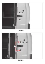
Page 4: ...PICTURE 2 PICTURE 3 P2 A5 ...
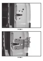
Page 5: ...PICTURE 4 PICTURE 5 A1 ...
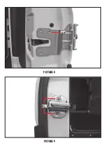
Page 6: ...PICTURE 6 PICTURE 7 A5 A6 ...
Page 7: ...PICTURE 8 PICTURE 9 A6 P3 ...
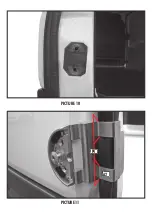
Page 8: ...PICTURE 10 PICTURE 11 P4 A2 ...
Page 9: ...PICTURE 12 PICTURE 13 P5 P6 ...
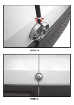
Page 10: ...PICTURE 14 PICTURE 15 P7 ...
Page 11: ...PICTURE 16 PICTURE 17 P8 ...
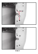
Page 12: ...PICTURE 18 PICTURE 19 A5 P9 ...
Page 13: ...PICTURE 20 PICTURE 21 A3 A5 A6 ...
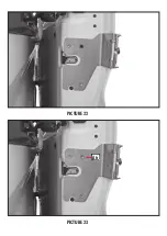
Page 14: ...PICTURE 22 PICTURE 23 A6 ...
Page 15: ...PICTURE 24 PICTURE 25 P10 P11 ...
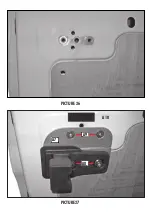
Page 16: ...PICTURE 27 PICTURE 26 A9 A7 A8 A10 ...
Page 17: ...PICTURE 28 PICTURE 29 P12 ...
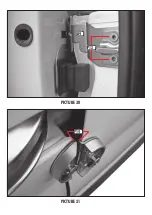
Page 18: ...PICTURE 30 PICTURE 31 P14 P13 A4 ...
Page 19: ...PICTURE 32 PICTURE 33 ...


