background image

Summary of Contents for 70-1D-2

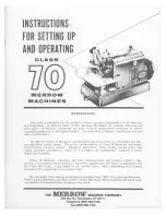
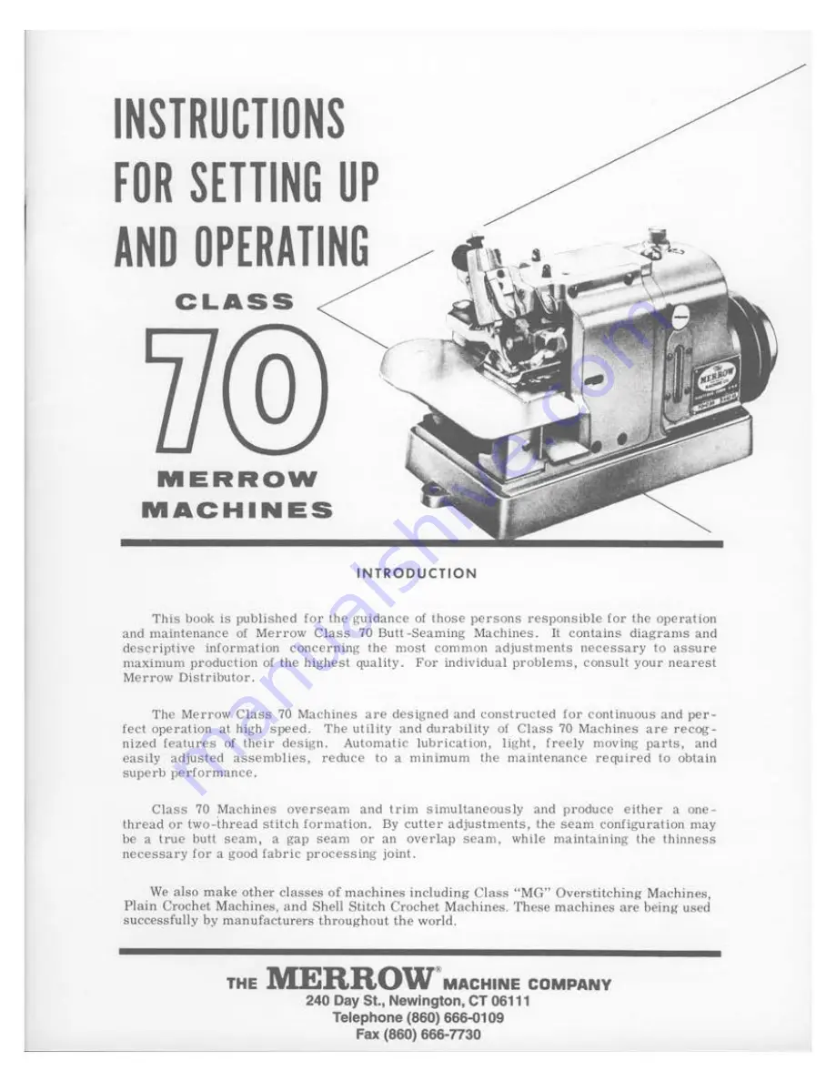
Page 1: ...recog nized features or their design Automatic lubrication light Crcely moving parts and easily adjusted assemblies reduce to a minimum the maintenance required to obtain superb performance Class 70...

Page 2: ...below a Needle P lates specify Machine Style 70 D3B 70 Y3B etc Machine mounting table railway rotary stand and the manufacturer of such mounting Type of seam butt gap overlap etc size of needle used...

Page 3: ...pring W P Stud M 324 1 Screw 10 Work Plote W P Plunger M 198 3 W P P Spring 27 42 CLASS 70 INSTRUCTION BOOK Heod Cop Screws 12 36 11 I 11 I I I 21 I INCHES Heod I I I I I I 1 2 3 4 5 MM Screws 121 83...

Page 4: ...catch under the cone or be otherwise retarded 8 Since oil has been drained from the machines before shipping the main reservoir must be filled before the machine is used Note section 14 SPEEDS The St...

Page 5: ...t 37 5 C is recommended To drain the oil dismount the machine and extend the feed mechanism end of the machine over the end of the table After providing a means of catching the oil unscrew the Oil Dra...

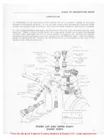
Page 6: ...faces of the main shafts on the left end of the machine the Needle Carrier Assembly the Upper Cutter Carrier Assembly and the Feed Mechanism 19 Some of the oil not fed into the Oil Bubbler Pipe is for...

Page 7: ...y LLC www supsew com CLASS 70 INSTRUCTION 8OOK Sc ew 131 83 I I I I S I I MACHINE BASE ASSEMBLY 0 0 1 1 J I I I J I 2 I INCHE 1 1 I I I I M 1 J 4 S Oil Gouge M 33 t 1 Oil Gouge Plate M 320 4 0 G P Goi...

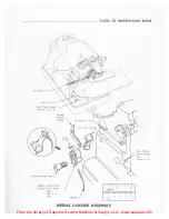
Page 8: ...e needle plate is large enough to accommodate the needle THE NEEDLE CARRIER 28 The Needle Carrier Assembly must be perfectly free lo swing upon its stud but must have no lateral movement This adjustme...

Page 9: ...Screws t2 52 6 Needle Thread Takeup Set Screw 12 l N C link Ass y Screw j 1 1 t Needle Cor icr Stud Needle Conier A ss y includes N C Collar Bolt N ut 4 Pin CLASS 70 INSTRUCTION BOOK Com Timing Screw...

Page 10: ...Lower Looper are nearly self setting but may need slight bending If it is necessary to bend a Looper always bend it slightly too far in the direction desired and flex the Looper back to position Othe...

Page 11: ...ke the Needle but the point of Needle should pass close to the back side of the Upper Looper at point C To effect this adjustment the Looper can be sprung up or down as well as sidewise 40 Turn the Ha...

Page 12: ...C Holder Clomp A 97 1 Upper Cutter lower Cutter Holder 6 6S U l C Holder Support Assembly Includes L C H Clomp M 66 3 l C H C Screw 86 i l C H Supporl Shim U C Clomp INCHES I I 2 3 MM Threod Culler 6...

Page 13: ...to contact the lower surface of the Presser Foot 50 Clamp the L C Holder to the width of trimming desired by Screw 86 3 16 Turn the machine over by hand and set the Upper Cutter so that in its lowest...

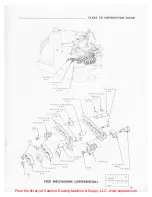
Page 14: ...ate Feed Dogs with their separate Feed Carriers and separate Feed Eccentrics When it is desired to prevent the edge of the fabric from being stretched or lengthened while seaming the Front Feed Dog is...

Page 15: ...OOK f t d Conif r Spoc r 6 313A Feed Come R M 74 3 foodO RI 1 iP NUT 2 f C l Bu hing UH M 79 J f cd f c nlt c ffl NUJ 7 feed f fflJ o RJ M 76 1 l Feed Comer l RI M 76 1 Sc rcw II I FEED MECHANISM DIFF...

Page 16: ...ng Feed Link Pivot M 351 1 to a position where it is totally below the mounting surface of F L P Support M 358 1 and sliding out F L Pivot Pin M 352 1 g The F L P ivot is removed by taking off Nut 4 3...

Page 17: ...From the library of Superior Sewing Machine Supply LLC www supsew com CLASS 70 INSTRUCTION BOOK 1 f lo _ f Hd pqw I I I I INCHES Y FEED MECHANISM 17...

Page 18: ...oviding accessibility to the Needle and Loopers 66 The Presser Foot Finger should be positioned upon the Presser Fool so that its left edge just covers the right edge of the slot in the needle plate I...

Page 19: ...in the Frame Cap and turn the Hand Wheel until both Looper Carrier Assemblies are al the extreme right hand position Then the Frame Cap Assembly may be readily pulled toward the operator and removed...

Page 20: ...ver any of the parts compiling this assembly are replaced this adjustment should be checked 72 The Cam Rolls for the Upper Looper Carrier Assembly are identical If excessive up and down looseness of t...

Page 21: ...out of the machine Note When replacing U S 0 M Holder M 137 5 place pointed projection on this part into the hole in U S Oil Collector M 137 3 4 Insert a 1 8 Screw several turns into the U S Oil Coll...

Page 22: ...ine L S 0 M Holder 6 9 32 may now be removed with a screw driver from its location between the Shafts j Before re assembling clean all parts including the oil holes and slots in the Frame k In re asse...

Page 23: ...1 2 3 4 S MM Foo1 lifter Screw 87 Plunge 37 97 R I REAR VIEW CLASS 70 INSTRUCTION BOOK P F l Roll Sc cw 90 P F l Stop Clomp A 278 Screw 16 Ya N ut 4 Screw 10 y N T Tension R od AHcmbly Specify Spring...

Page 24: ...uperior Sewing Machine Supply LLC www supsew com fi THE 240 DAY STREET MERRO l K NEWINGTON CT 06111 W Telephone 860 666 0109 MACHINE COMPANY Fax 860 666 TT30 For worldwide markets American made since...

Reviews: