background image


14 


MERRY TILLER SERVICE BULLETIN 


TIME TO CHANGE THE TINE SHAFT SEALS 


Tine Shaft Seal Replacement Instructions 

 
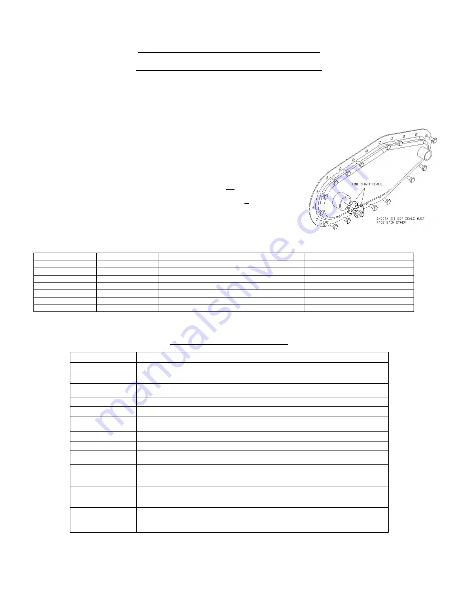
It is extremely important that the oil seals on the tiller transmission be inspected and replaced regularly to ensure proper lubrication and to 
prevent dirt from entering the transmission.  Both sides of the tine shaft have two oil seals.  These seals are inserted back to back over the tine 
shaft.  The inner seal faces into the transmission and is designed to keep lubricant from escaping from the transmission.  The outer seal faces 
outward and is 

designed to keep dirt out of the transmission.  The Merry Tiller transmission is lubricated with heavy “00” grease.  If the seals 

fail, it may not be noticed due to the heavy consistency of the grease.  This is the best possible 
lubricant available and will add years of life to your Merry Tiller.  Seals should be inspected 
regularly and replaced as needed or before periods of expected extended use. 
 
To replace the seals proceed as follows. 
 

1. 

Take a screwdriver or awl and hammer along the tine shaft until you can pry the first 
seal out. 

2. 

Repeat and take the second seal out. 

3. 

Place the new seal on the tine shaft with smooth side facing out, and press into place.  
(Note:  A 1 ½” ID piece of plastic pipe works great to do this). 

4. 

Place the second seal on the tine shaft with the smooth side facing in, and press into 
place. 

5. 

Repeat to other side of the transmission. 

Note:  It is very important that the smooth side of the two seals be against each other. 


Replacement Parts 


PART # 

QTY 

WHERE USED 

DESCRIPTION 


708-3241 

MINNIE 

OIL SEAL 

708-3241-10 

10 

MINNIE 

OIL SEAL 

– 10 PACK 

708-3241-50 

50 

MINNIE 

OIL SEAL 

– 50 PACK 

706-0344 

SUBURBAN/INTERNATIONAL 

OIL SEAL 

706-0344-10 

10 

SUBURBAN/INTERNATIONAL 

OIL SEAL 

– 10 PACK 

706-0344-50 

50 

SUBURBAN/INTERNATIONAL 

OIL SEAL 

– 50 PACK 


MAINTENANCE SCHEDULE 


Frequency 

Service required 

After every use 

Inspect belts & pulleys for proper alignment and excessive wear 


Check operation of belt and idler, make sure tines stop & start correctly 


Inspect transmission for any leakage, check all bolts for tightness. Pay particular attention to 
center bolt that secures the transmission to the frame rails  


Check tines for wear and excessive play, make sure no pins are missing 


Perform normal engine maintenance 

Every 150 hours 

Inspect transmission case assembly, conduct test for excessive travel, (see attached). Check 
for excessive wear on case halves 


Check tine shaft and drive shaft for up and down play, if loose replace bearings.  


If transmission is OK replace tine shaft and drive shaft seals  


Inspect tines for wear, if cutting corner is rounded replace tines. Check pin holes for 
elongating and wear, make sure no pins are missing   


Anytime the transmission is unbolted from the frame rails it is necessary to secure the internal 
sprockets with a 5/16" rod cut to the same width of the transmission case. It is possible for 
the internal sprockets to move if not secured during service 

 Every 600 hours 

Remove transmission for internal inspection.  Disassemble and inspect all parts for wear.  
Clean all parts, replace worn parts as needed, relubricate with approx. 9 oz.“00” grease.  
Reassemble with new case gasket and reinstall on tiller. 


Anytime the transmission is unbolted from the frame rails it is necessary to secure the internal 
sprockets with a 5/16" rod cut to the same width of the transmission case. It is possible for 
the internal sprockets to move if not secured during service 


Summary of Contents for IT950IC

Page 1: ...AUTION Before using this product read this manual and follow all Safety Rules and Operating Instructions MACKISSIC INC P O BOX 111 PARKER FORD PA 19457 0111 PHONE 610 495 7181 e mail info mackissic com FAX 610 495 5951 www mackissic com P N 710 3402 12 22 16 ...

Page 2: ...r Drawing 19 Warranty 20 MERRY TILLER ACCESSORIES AVAILABLE WHEREVER MERRY TILLER PRODUCTS ARE SOLD MT 951 MT 952 MT 956 MT 1701 MT 1702 MT 1703 MT 1812 MT 1813 MT 2492 MT 2857 MT 7801 MT 7802 MT 7875 Finger Tine Assemblies Right and Left Inside Finger Tine Assemblies Right and Left Outside Pick Tine Assemblies 1 set Slasher Tine Assemblies Right and Left Inside Slasher Tine Assemblies Right and L...

Page 3: ...ng soil and use only approved attachments and accessories It is designed for this use and any other use may cause injury DANGER Rotating tines and belt Keep hands and feet out of tines and belt area while machine is running DANGER This machine can CRUSH CUT and SEVER parts of your body if they enter the operating areas of the garden tiller Make certain that all safety labels on this equipment are ...

Page 4: ...Remove or rotate wheels to up position 2 Adjust drag bar for desired depth 3 Stand between handlebars 4 Allow clutch lever to drop into disengaged position 5 Move throttle lever to run position 6 Reach forward to set choke lever to choke position 7 Hold left handlebar with left hand and pull starter rope with right hand 8 As engine starts return choke lever to run position and adjust throttle for ...

Page 5: ...structions Disengage clutch before starting the engine motor Never attempt to make any adjustments while the engine motor is running except where specifically recommended by the manufacturer DO NOT put hands or feet near or under rotating parts Exercise extreme caution when operating on or crossing gravel drives walks or roads Stay alert for hidden hazards of traffic Do not carry passengers Stop t...

Page 6: ... all safety guards and shields are in proper position These safety devices are for your protection Never operate your tiller in poor mechanical condition or when in need of repair Periodically check and keep all nuts bolts and screws tight to be sure the equipment is in safe working condition Inspect the belt each time you use the unit Look for damage worn areas or tears Do not use the unit if thi...

Page 7: ... should be done on a clean level surface STEP II Attaching Handles Cross Brace and Tie Bars 1 Attach lower ends of handles item 31 34 pg 20 to frame rails item 14 15 pg 18 Use the 5 16 18 x 1 1 4 HHCS item 51 pg 20 and the 5 16 18 nylock nut item 41 pg 20 to attach each handle Do not completely tighten the bolts and nuts at this time 2 Remove the two long bolts and whiz nuts on the transmission wh...

Page 8: ... clutch control lever item 31B pg 20 Now attach the clutch cable chain to the spring 4 Disconnect the spark plug Grasp the starter pull cord and pull it 6 past cross brace String the cord into eye of pull cord holder from the bolt bag Put the pull cord holder through the hole on the right hand handle above the cross brace This is illustrated as 54 pg 20 Secure with 1 4 20 nylock locknut item 5 pg ...

Page 9: ...way from the area of the spill Avoid creating any source of ignition until gasoline vapors have disappeared CAUTION Experience indicates that alcohol blended fuels gasohol ethanol methanol can attract moisture which leads to separation and formation of acids during storage Acidic gas can damage the fuel system or an entire engine while in storage To avoid engine problems the fuel system should be ...

Page 10: ...f tines to provide tilling widths of 14 and 26 A third optional tine extension is available to provide for a maximum tilling width of 37 If using the optional tine extensions install the tine tube tine extension and the outside tine per the drawing below In extreme soil conditions the recommended tilling width is 26 When adding and removing tines it is important to make sure all tines have the sha...

Page 11: ...g and operating the machine 9 If the unit should start to VIBRATE abnormally STOP the engine motor and check immediately for the cause Vibration is generally a warning of trouble 10 STOP the engine motor when leaving the operating position Disconnect the spark plug wire before unclogging the tines and when making any repairs adjustments and inspections 11 Take all possible precautions when leaving...

Page 12: ...ockwise to tighten clutch After making any change in position of adjustment link re tighten nut 3 Additional adjustment can also be made by loosening the four bolts item 8 pg 17 holding the engine to the engine mounts items 14 15 pg 17 and sliding the engine forward or backward as needed Re tighten engine mount bolts This adjustment is almost never needed and should not be made unless all other ad...

Page 13: ... it is advisable to take your tiller to an authorized MERRY TILLER dealer especially if there are signs of excessive wear Following are some suggestions that will help to determine the amount of wear 1 Before removing the transmission case from the tiller turn the large pulley by hand and observe whether or not the rotor shaft also turns If it does not or if the pulley turns freely check to be cer...

Page 14: ...8 3241 50 50 MINNIE OIL SEAL 50 PACK 706 0344 1 SUBURBAN INTERNATIONAL OIL SEAL 706 0344 10 10 SUBURBAN INTERNATIONAL OIL SEAL 10 PACK 706 0344 50 50 SUBURBAN INTERNATIONAL OIL SEAL 50 PACK MAINTENANCE SCHEDULE Frequency Service required After every use Inspect belts pulleys for proper alignment and excessive wear Check operation of belt and idler make sure tines stop start correctly Inspect trans...

Page 15: ... may occur Remove the spark plug pour approximately one tablespoon of engine oil into cylinder and crank slowly to distribute oil Replace the spark plug Use fresh fuel next season Do not store gasoline from one season to another NOTE Fuel stabilizer is an acceptable alternative in minimizing the formation of fuel gum deposits during storage Fuel Stabilizer Follow the mix ratio found on stabilizer ...

Page 16: ...16 ...

Page 17: ...ing Drive Shaft Seal R H Case Half Assembly includes items 2A to 2D Soft Plug Tine Shaft Bearing Oil Seal Bearing Gasket Roller Chain 50 40 Pitch 5 16 18 x 2 1 2 HHCS GR5 5 16 18 Nylock Locknut assembly 5 16 18 Whiz Locknut parts transmission Caplug Idler Sprocket Inner Race Tine Shaft Weldment Roller Chain 35 44 Pitch Roller Chain 40 40 Pitch Tine Shaft Spacer Upper Idler Sprocket Assembly includ...

Page 18: ...18 ...

Page 19: ...1 1 4 HHCS GR5 5 16 18 x 1 3 4 HHCS GR5 5 16 18 x 1 HHCS GR5 Engine mount spacer 5 16 18 x 3 HHCS GR5 3 16 x 3 16 x 1 Shaft Key Hitch L H Engine Mount R H Engine Mount Belt Release Weldment 5 16 24 x 3 4 HHCS GR5 2 Double A Pulley 6 Double A Pulley Belt 3 16 x 3 16 x 1 Key Clevis Pin 1 8 Hair Spring Cotter Idler Arm Idler Pulley 5 16 Flat Washer 3 8 16 Hex Nut 1 4 Flat Washer Rear Bracket Belt Cov...

Page 20: ...54 Clutch Control Lever 1 31C 706 0630 Handle Grip 1 31D 090 0057 20 x 1 1 2 HHCS 1 31D 090 0470 20 Nylock Locknut 1 32 706 1539 10 32 Kep Nut 2 33 090 0400 10 32 x 1 1 4 RD HD Mach Screw 2 34 706 2632 L H Handle Assembly includes items 34B 1 34B 706 0630 Handle Grip 1 41 090 0460 5 16 Nylock Nut 4 43 706 0152 Clutch Spring 1 48 090 0066 5 16 18 x 3 4 HHCS 2 50 706 2243 Cable Guide 2 51 090 0089 5...

Page 21: ...21 ...

Page 22: ...ssembled or installed as specified in the owner s manual The warranty does not cover any product that has been altered or modified In addition the warranty does not extend to repairs made necessary by normal wear or by the use of parts or accessories which in the judgment of MacKissic Inc are either incompatible with the MacKissic product or adversely affect its operation performance or durability...

Reviews: