29
How to mount the push-button
|
Note for the electrical installer:
Ensure that you note the
settings you have made in the ETS which are important for the
user in the configuration table (see „Presettings table", p. 46)
because not all parameters that can be set are shown in the
display of the push-button.
The Flush-mounted module must be mounted and have a physical
address.
2-fold push-button
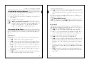
You need a Merten Frame System M to install the 2-fold push-button.
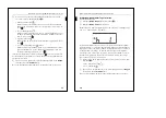
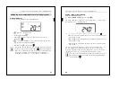
1
Figure
!
: Insert push-button
B
into frame
A
.
2
Figure
§
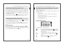
: Attach the push-button with Frame
B
onto Flush-
mounted module
A
. Ensure that the contact pins on the back are
not bent, but fit cleanly into the pin strip of the Flush-mounted
module.
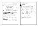
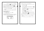
3
Figure
$
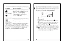
: Remove the display cover carefully from the housing by
unscrewing top left and right with a flat screwdriver.
4
Figure
%
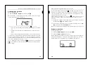
: For safe dismounting, secure the push-button to the
retaining ring of the Flush-mounted module with screw
A
provided
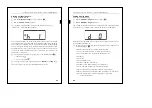
5
Figure
&
: Place the display cover in the housing bottom first,
pressing it firmly left and right simultaneously.
Now you can identify the labelling field (see Section „How to label the
push-button", p. 31).
|
Note on dismounting:
In order to be able to remove the push-button from the Flush-
mounted module, you first have to remove screw
% A
(dismounting safety feature).
How to mount the push-button
30
How to mount the push-button
4-fold push-button
To mount the 4-gang push-button, you need a Merten 2-gang frame
without central bridge piece, M-PLAN (art. no. 587300 ..) design.
Mounting is not possible with any other frame.
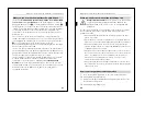
1
Figure
(
: Stick the two Velcro stickers together with the smaller in
the centre of the larger.
2
Remove the adhesive surface of the smaller sticker and stick it in the
notch on the back of the push-button housing.
3
Remove the adhesive surface of the larger sticker.
4
Figure
„
: Insert push-button
B
into frame
A
.
5
Figure
§
: Attach the push-button with Frame
B
onto Flush-
mounted module
A
. Ensure that the contact pins on the back are
not bent, but fit cleanly into the pin strip of the Flush-mounted
module.
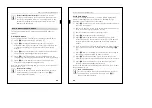
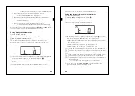
6
Press the lower part of the push-button against the wall so that the
Velcro sticker on the back remains attached to the wall (Figure
"
E
).
7
Figure
$
: Remove the display cover carefully from the housing by
unscrewing top left and right with a flat screwdriver.
8
Figure
%
: For safe dismounting, secure the push-button to the
retaining ring of the Flush-mounted module with the screw provided.
9
Figure
&
: Place the display cover in the housing bottom first,
pressing it firmly left and right simultaneously.
Now you can affix labels in the labelling field (see section „How to label
the push-button", p. 31).
|
Note on dismounting:
In order to be able to remove the push-button from the Flush-
mounted module, you first have to remove screw
% A
(dismounting safety feature).


