7I92 2
HARDWARE CONFIGURATION
GENERAL
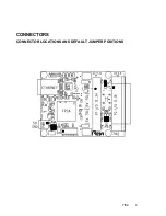
Hardware setup jumper positions assume that the 7I92 card is oriented in an upright
position, that is, with the Ethernet connector towards the left and the I/O connectors
towards the right.
CONNECTOR 5V POWER
The 7I92 has the option to supply 5V power from the to the breakout board. This
option is used by all Mesa breakout boards to simplify wiring. The option uses 4 parallel
cable signals that are normally used as grounds for supplying 5V to the remote breakout
board (DB25 pins 22,23,24 and 25). These pins are AC bypassed on both the 7I92 and
Mesa breakout cards so do not compromise AC signal integrity. The 5V power option is
individually selectable for each of the four I/O connectors. The breakout 5V power is
protected by per connector PTC devices so will not cause damage to the 7I92 or system
if accidentally shorted. This option should only be enabled for Mesa breakout boards or
boards specifically wired to accept 5V power on DB25 pins 22 through 25. When the option
is disabled DB25 pins 22 through 25 are grounded. Jumper W3 sets the power option on
header P1, and W4 sets the power option on DB25 connector P2.
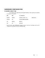
JUMPER
POS
FUNCTION
W3,W4
UP
BREAKOUT POWER ENABLED
W3,W4
DOWN
BREAKOUT POWER DISABLED (DEFAULT)
5V I/O TOLERANCE
The FPGA used on the 7I92 has a 4V absolute maximum input voltage
specification. To allow interfacing with 5V inputs, the 7I92 has bus switches on all I/O pins.
The bus switches work by turning off when the input voltage exceeds a preset threshold.
The 5V I/O tolerance option is the default and should normally be left enabled.
For high speed applications where only 3.3V maximum signals are present and
overshoot clamping is desired, the 5V I/O tolerance option can be disabled. W1 controls
the 5V I/O tolerance option. When W1 is on the default UP position, 5V tolerance mode
is enabled. When W1 is in the DOWN position, 5V tolerance mode is disabled. Note that
W4 controls 5V tolerance on both I/O connectors.
PULLUP VOLTAGE
Jumper W1 also selects the I/O connector pull-up resistor voltage, When W1 is in
the UP position the 4.7K I/O pullup resistor common is connected to 5V, When W1 is in
the down position, The 4.7K I/O pullup resistor common is connected to 3.3V.


