12
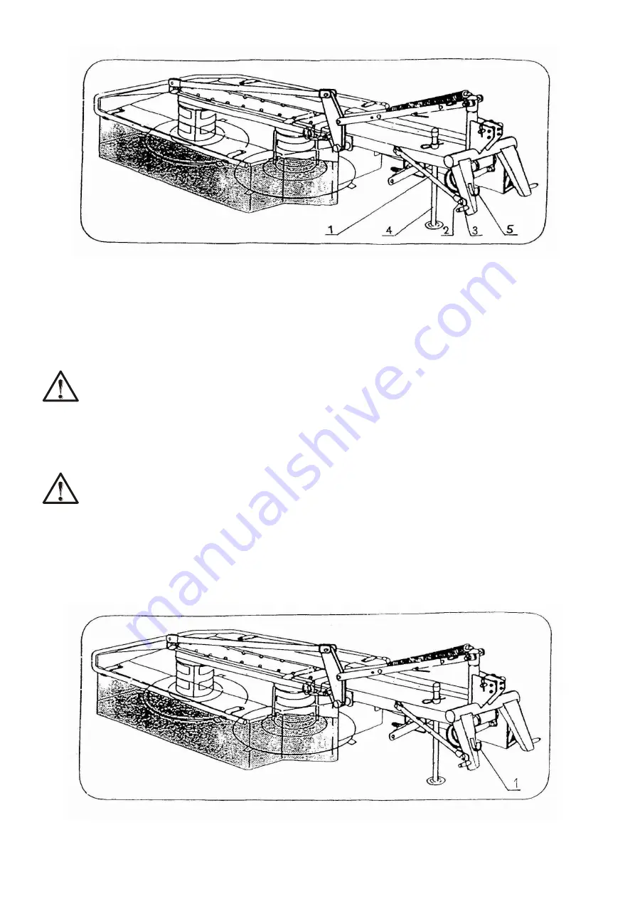
Fig. 3. Linking of the mower and the tractor into a working unit.
1 – transport rod, 2 – mandrel, 3 – pin, 4 – support, 5 – yoke.
5.2.2. ASSEMBLING A PTO DRIVE SHAFT
For driving the mower use the PTO drive shaft of the type given in the manual.
CAUTION!
Always use shields of the PTO shaft and tractor’s drive shaft. Shields of PTO shaft must be
protected against turning according to the PTO shaft service manual.
5.2.3. TRANSPORTING THE MOWER MOUTED ON A TRACTOR.
CAUTION !
During the transport on public roads the mower should be equipped with cautionary
lighting panels according to obligatory home traffic regulations.
For driving to the workplace, disconnect the jointed shaft of the mower from the PTO shaft of
the tractor and rest it on the yoke 1. During transport the mower should be raised on a hydraulic
lift with the cutting tool turned backwards for safety.
Fig. 4. Mower in transport position.
1 – yoke.
Summary of Contents for Z 175-1
Page 1: ......
Page 19: ...18 NOTES ...
Page 21: ...20 Fig 11 COMPLETE MAIN DRIVE ...
Page 23: ...22 Fig 12 COMPLETE INTERMEDIATE FRAME ...
Page 25: ...24 Fig 13 THREE POINT FRAME ASSEMBLY ...
Page 27: ...26 Fig 14 COMPLETE MAIN FRAME ...
Page 29: ...28 Fig 15 DRUMS ASSEMBLY ...
Page 31: ...30 Fig 16 COMPLETE HOUSING ...
Page 33: ...32 NOTES ...


