BA2070/03/16
Messko
13
2
Product specification
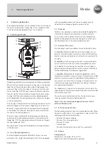
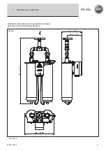
The dehydrating breather can be mounted either on the pipe of
the oil conservator with a flange (Fig. 1/1) as standard or with
2 side mounting rods (appendix, Fig. 7) as an option.
2 .1 Function specification
Dehydrating breathers work according to the following principle.
When the oil conservator suctions in air (e.g., due to the reduced
load), the air flows through a filter made of high-grade steel
wire mesh (Fig. 1/4) to the inside of the device. This filter and
the dust cap (Fig. 1/5) filter dust, sand and other dirt particles
from the air. The filtered air flows through the desiccant cham-
ber (Fig. 1/8) filled with colorless, moisture adsorbing pellets
and is dehydrated. The dehydrated air rises further via the pipe
in the oil conservator.
A sensor (Fig. 1/10) monitors the air flowing by to determine the
saturation degree of the desiccant. Depending on its state, the
desiccant is regenerated with the heating elements integrated
in the desiccant container. A temperature sensor monitors the
function of the heating elements.
The water vapor created by the baking process condenses by
convection in the dehydrating breather on the bottom metal
flange (Fig. 1/7). The condensed water exits the device through
the high-grade steel filter.
No maintenance is required for replacement and regeneration
of the desiccant.
2 .2 Twin Dehydrating Breather
The twin dehydrating breather (DB 200 D-T) uses the same
principle as the „single“ dehydrating breather. This is equipped
with two parallel desiccant containers to enable them to
handle the air exchange of greater amounts of oil.
2 .3 Desiccant
Colorless, non-poisonous, moisture-adsorbing Silicagel pellets
which do not change their color when a moisture saturati-
on occurs are used as desiccant material in the dehydrating
breather. Silicagel pellets which do change their color have a
limited lifetime due to the chemical additives used.
2 .4 Control of the heater
The following 3 types are available for controlling the heater.
α
-controller: Recommended for use on tap changers, arc su-
pression coils and traction transformers. Here the dehydrating
breather is baked out based on its state which is monitored for
humidity.
β
-controller: A self-learning system that is recommended for
use on transformers with cyclic loads (see applications, table
2). In addition to monitoring the humidity, a time window is
determined here during which the oil conservator exhales and
the dehumidification chambers are regenerated.
γ
-controller:
Recommended for special applications such as
transformers installed in caverns, furnace transformers and GSU
machine transformers with non-periodic breathing behavior. If
the moisture content of the air flowing in the direction of the
transformer exceeds a specified value, the silica gel chambers
are regenerated alternately.
For redundancy, a time control is also present which starts the
regeneration of the desiccant at predetermined intervals should
the moisture sensor fail.
The control unit and the terminals for the electrical connec-
tions are located in the terminal box (Fig. 1/9).
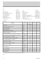
Table 2 lists the recommended application areas for the
different MTraB versions .
2 .5 Self-monitoring function
The dehydrating breather has a self-monitoring function. When
the device malfunctions, this is reported by a relay contact. The
following malfunctions are detected:
- Failure of the power voltage
- Failure of the silicon gel heater
- Failure of a sensor
- Internal error
- Failure of the ball valve (
only with the
γ
-controller)
2 .6 Outputs
Analog output:
Temperature in the pipe -40 to +80 °C;
Signal 4 to 20 mA standard, others optional;
2
Product specification
1
2
3
4
5
6
7
8
9
10
11
12
Fig .
1
Summary of Contents for MTraB DB100
Page 2: ...BA2070 03 16 2 ...
Page 23: ...BA2070 03 16 Messko 23 ...


