BA2070/03/16
Messko
15
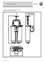
The twin dehydrating breather is mounted like the „single“
dehydrating breather. Do not forget the larger dimensions of
the twin dehydrating breather (Fig. 8) when you are planning
installation.
4 Electrical connection
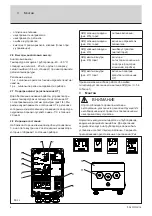
To wire the hydrating breather, open the terminal box (Fig. 1/9).
The cover of the terminal box (Fig. 2/10) is grounded with a
contact lead (Fig. 2/9) and is thus protected against falling to
the ground.
The wiring is done with cable glands (Fig. 2/11) M20 x 1.5 or
through a 1/2“ - 14NPT coupling. Remove the cable sheaths
accordingly and strip the insulation to a length of 7 mm (1/4“).
4 .1 Power voltage
Connect the voltage supply (as per the nameplate) to terminals
2 (L) and 3 (N) and the protective conductor to 1 (PE). The
voltage supply should be protected with a 16A automatic
circuit breaker.
For the device version with
γ
controller (DB200G), the voltage is
supplied via the 2(L) and 3(N) connection terminals in the housing
cover of the terminal box (see appendix Fig. 9).
4 .2 Relay
The error relay (normally closed contact; failsafe) is connected
to terminals 4 and 5. When a device error occurs or the voltage
supply is not connected or not switched on, the contact closes.
The error relay falls after a time-delay (> 7 seconds) before the
voltage supply is switched off so that brief interruptions of the
voltage supply do not generate an error message.
The signaling contact for the regeneration procedure (change-
over contact) is connected to terminals 6, 7 and 8. When the
desiccant is regenerated, contact between terminals 7 and 8
is made.
4 .3 Analog output
The analog output is connected to terminal 9(+) and 10(-).
We recommend using a shielded cable for the connection and
connecting the shield to terminal 11.
4 .4 Device grounding
The device can be grounded with the M12 grounding screw
(Fig. 1/10). When potential differences are to be expected bet-
ween ground and the protective conductor (PE), the grounding
connection should not be used. An insulated device model is
available as an option. Contact Messko for further information.
5 Operation and maintenance
5 .1 Device self test
After installation and connection, the dehydrating breather
is ready for operation. Upon connection of the power supply
the device automatically performs a device self test (approx.
15 sec.). During the entire self test, the LEDs located outside
flash in succession while the function of the relays (except the
error relay) and the sensors is being checked. After a self-test
the device switches to the standard control software which will
be indicated by the green LED. When an error is detected, this
is indicated (see chapter 5.4 Fault monitoring). An expanded
device self test can be started with the test button which is
available as an option (see chapter 5.2).
5 .2 Test button (optional)
The test button which is available as an option can be used to
check the following functions:
- Internal functions such as during switch on (device self test)
- SiO2 heater.
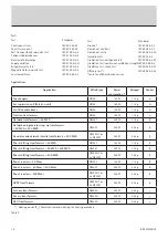
Errors are indicated as specified in table 1.
The function test takes approx. 5 minutes. Afterwards, if opera-
tion is free of errors, the device returns to its normal routine.
5 .3 Maintenance
During regular checks of the transformer, we recommend per-
forming the following checks on the dehydrating breather:
• Check the exterior condition of the device for dirt and
damage (especially the dust cap and the high-grade steel
filter).
4
Electrical connection
5
Operation and maintenance
WARNING
Hazardous electrical voltages!
It is imperative to deactivate the power supply before
opening the terminal box and during wiring of the device.
CAUTION
Electrical connections may only be carried out by qualified,
skilled personnel trained in the applicable safety regulations
of the relevant country.
CAUTION
Do not connect terminal 2a (L‘)! It must only be connected
when an optional adapter transformer is used.
NOTE
After a regeneration procedure, the SiO2 heater cannot
be checked again for the next 8 hours. If the test button
is pressed during this time, the outside LEDs flash 10 times
and a reduced test is initiated without the SiO2 heater
check.
Summary of Contents for MTraB DB100
Page 2: ...BA2070 03 16 2 ...
Page 23: ...BA2070 03 16 Messko 23 ...


