


10
11
Please read the instructions thoroughly before using the pump! Otherwise you may not use it!
This appliance is not suitable for use by persons (including children) with limited physical, sensory or mental
capabilities or lacking experience and/or knowledge, except if they are supervised by a person responsible
for their safety or have been instructed in the use of the appliance.
Children should be supervised in order to make sure that they do not play with the appliance.
Construction
These modern, powerful pumps are equipped with a single-phase alternating-current motor (canned motor
with capacitor). The motor is waterproof encapsulated in synthetic resin (IP68) and provided with an
overload protection.
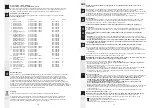
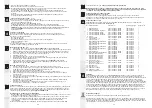
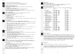
Please refer to the type plate for technical specifi cations or the table on page 1.
Use
These pumps are designed for the transport of water, for the operation
of fi lter systems,water displays, waterfalls, etc., as well as for oxygenating and circulating the water.
Area of application: garden ponds, fi shponds, outdoor and patio fountains!
-
Attention!
Use in garden ponds and their protected zone is permitted only if the installation is
performed in compliance with the applicable regulations. Please consult a licensed electrician.
-
Before performing any work on the pump, the fountain, or the pond, disconnect the mains
plug. Do not operate the pump if people are in the water! (disconnect the pump from the power
source)
Area of application: swimming pond or swimming pool (if people are in the water)!
Pump suitable for installation and operation in systems and rooms according to DIN VDE 0100 Part 702 and
Part 737, if the erection requirements per DIN VDE 100 and the manufacturer’s specifi cations (assembly
and operating instructions) are followed.
Installation of these pumps at swimming ponds or swimming pools must comply with the following
standards: DIN EN 13451 Part 1 to Part 8, and DIN VDE 0100 Part 702 and Part 737.
Attention! Here operation of the pump is permitted only if the pump is permanently installed outside
of the water at least 2 m or more away from the pool.
The following measures must be undertaken:
(see fi g. 2)
- Build a shaft with pedestal for the pump,
at least 2 m away from the edge of the water.
- Protect the shaft with a cover.
- To protect the pump from fl ooding build a drain for the shaft.
- Attach the pump to the pedestal with screws.
- Install a “M” metal socket in the suction line, toward the pump, to connect to the equipotential bonding
of the swimming pond/swimming pool system!
- Please consult a licensed electrician. Also refer to “Non submersible use” and “Safety Measures.”
Safety measures
- Before use: Check whether mains lead and plug are intact.
- Mains voltage and kind of current have to conform to the information on the type plate.
-
The pump may only be connected to a proper earthing-contact type socket through a residual
current device (RCD, 30 mA).
-
The connection box should be located in a water-protected area and at least 2 m away from the
edge of the water (see fi g. 1).
- Always keep the plug dry.
-
Important!
If the mains lead or the motor housing are damaged, the pump cannot be used anymore. It
cannot be repaired since the lead is permanently encapsulated in the motor housing.
- Do never hang up or transport the pump by the mains lead.
Start-up (see fi g. 1 - 3)
Important! Do not let the pump run „dry“. This could cause damages to the appliance.
- Immerse the pump completely in your pond. This causes the pump body to be fi lled with water.
- A minimum water depth of 25 cm is required for underwater operation to avoid the pump taking in air.
- The maximum depth for submerged operation of the
2 m
pump is 2 m!
- The water temperature may not exceed 35°C.
- The pump must be protected from frost.
- The pump is switched on by putting the plug in the socket.
- To prevent the pump bpowerming unnecessarily dirty, place it above the sludge deposits in your pond, in a
fi rm and horizontal position (on a stone slab)!
- A range of accessories may be fi tted onto the threaded connections of the pump.
- The supplied screen inserts are suffi cient as protection from intake in clear water.
GB
- Suitable fountain jets can be found in our range of accessoires
(catalog)
.
“Non submersible use” (see fi g. 2 + 3)
The pump can be used in a nonsubmerged type application.
- Position the pump below the surface of the water, at the side of the pond so that the water can fl ow into
the pump (not self-priming).
- Remove strainer insert (8)
(see fi g. 4 + 5)
.
- Connect suction hose (S) and pressure hose (D) to the pump. Connection should be watertight.
- Suction hose and pump must be fi lled with water before switching-on.
-
TIP!
To prevent the pump bpowerming clogged, provide the suction hose with a pre fi lter
Art.-No. 168 / 009051
covered in our range of accessories.
Overload protection
In case the pump is bpowerming overheated the built-in thermal overload trip switches it off.
The pump must cool down.
The pump will not start automatically without the necessary controlling when it is cool.
Check the following operating conditions:
- Is there a suffi cient water supply?
- Has the fi lter bpowerme clogged?
- Has dirt entered the pump housing (Follow the cleaning instructions below)?
- Have hoses or jets bpowerme clogged?
- Has the pump cooled down?
As soon as you have solved the problems, you can switch on the pump again by pulling the plug out of the
socket and putting it in again after a short time (1 min.)
Dismantling (see fi g. 4 - 8)
1. Follow the safety measures.
Disconnect pump from mains!
2. Grasp the two clips (20 + 21) on the front of the pump, on the lower end, and turn them upward and
forward.
3. Push the two fl aps at the front side of the pump inwards. Lift and remove upper shell (1). Now the
screen inserts on the front (8), on the right side (7) and on the left side (5) work loose.
4. Remove the entire pump (10) with pump housing (12) from the lower shell (2).
5. Loosen the 4 screws (18).
6. Pull apart pump housing (12) and motor housing (10).
7. Remove rotor assembly (15) from motor housing (10). Take care of the O-ring (16) on the motor
housing (10).
8. Clean all parts with clear water and a soft sponge.
Note!
In case of massive calcination please use
Messner decalcifi er for pumps
art.-no. 168 / 009115
.
Assembly (see fi g. 4 - 8)
1. Push the O-ring (16) onto the starting point on the motor housing (10).
2. Carefully slide the rotor assembly (15) into the motor housing (10) and twist the bearing cover so that
the two holes fi t onto the pins on the motor housing (10).
3. Check whether the rotor assembly can be rotated easily.
4. Check the position of the O-ring (16) on the motor housing (10).
5. Put the pump housing (12) on the motor housing (10) and attach it fi rmly and evenly with the 4
screws (18).
6. Set the pump (10) into the base tray (2).
7. Attach the upper shell (1) to the rear hook of the lower shell (2) and lock it into the front fl aps.
8. Grasp the two clips (20 + 21) on the lower end and turn them to the rear, this locks the upper shell (1)
and the lower shell (2).
9. Insert the respective screen inserts into the openings on top (3) and on the left (5) or on the
front (8) and on the right (7).
Maintenance
In order to prolong the service life of your pump signifi cantly and to keep it in sound operating condition, it is
rpowermmended to carry out maintenance and cleanup regularly.
This can be done by everyone, quickly and easily.
See „Dismantling/Assembly“
Servicing intervals
- In the beginning check proper performance of your pump every day. If necessary, clean the fi lters.
- Since servicing intervals (complete cleaning) will vary depending on the level of pond pollution, repeat the
periodic service to your pump in accordance with the pollution of the pond water .
Should you determine that there are
damaged or worn parts
, replace them.
See „Spare parts“
Important! When used in calcareous water, the rotor assembly (15) and the stainless steel can split
tube in the motor housing (10) should be cleaned at regular intervals.


