


10
11
Please read these instructions thoroughly, before using the pump!
This appliance is not suitable for use by persons (including children) with limited physical, sensory or mental
capabilities or lacking experience and/or knowledge, except if they are supervised by a person responsible
for their safety or have been instructed in the use of the appliance.
Children should be supervised in order to make sure that they do not play with the appliance.
Use:
Centrifugal pump for submersible usage with resin encapsulated motor.
The pump is suitable for use in water, e.g. for garden ponds, fountains, terraced fountains, indoor fountains,
in fi shponds, for the operation of fi lter systems, fl owing brooks etc. as well as for circulating and oxygenating
water.
The pump may not be used in or on the side of swimming pools!
Please refer to the type plate for technical specifi cations or the table on page 1.
Safety measures
-
Caution!
It may only be used in garden ponds and in their protection area if the electrical installations
have been set up to comply with the code‘s requirements. Please contact an electrician.
- Before use: Check whether mains connection and plug are intact.
- Mains voltage and type of current have to correspond to the data on the type plate.
-
The pump has to be connected to a regular safety plug socket through a residual current
device (RCD, 30 mA).
- The connection box should be located in a water-protected area. It should be at least 2 m away from the
edge of the pond
(see fi g.1)
.
- Keep the plug dry!
-
Pull out mains plug before starting to work on the pump, fountain or pond. It is not allowed to
run the pump when people are inside the water (disconnect the pump)!
-
Important!
If the mains connection or the motor housing is damaged, the pump cannot be used
anymore. It cannot be repaired since the connection is cast into the motor housing.
- Never hang up or transport the pump by the cable!
-
Operate the pump only when it is immersed in water!
Start-up (see fi g. 1, 4 + 6)
Important! Do not let the pump run dry. This could cause damage to the appliance.
- Immerse the pump completely in your pond. This causes the pump body to be fi lled with water.
- A minimum water depth of 12 cm is required for underwater operation to avoid the pump taking in air.
- The maximum depth for submerged operation of the
2 m
pump is 2 m!
- The water temperature should not exceed 35°C.
-
Do not let the pump freeze in the wintertime.
- The pump is switched on by putting the plug in the socket.
- To prevent the pump becoming unnecessarily dirty, place it above the mud in your pond, in a fi rm and
horizontal position (on a brick)!
- A range of accessories may be fi tted onto the threaded connection of the pump.
- Running in conjunction with fountain jets, the pump should be positioned fi rmly and horizontally (on a
brick).
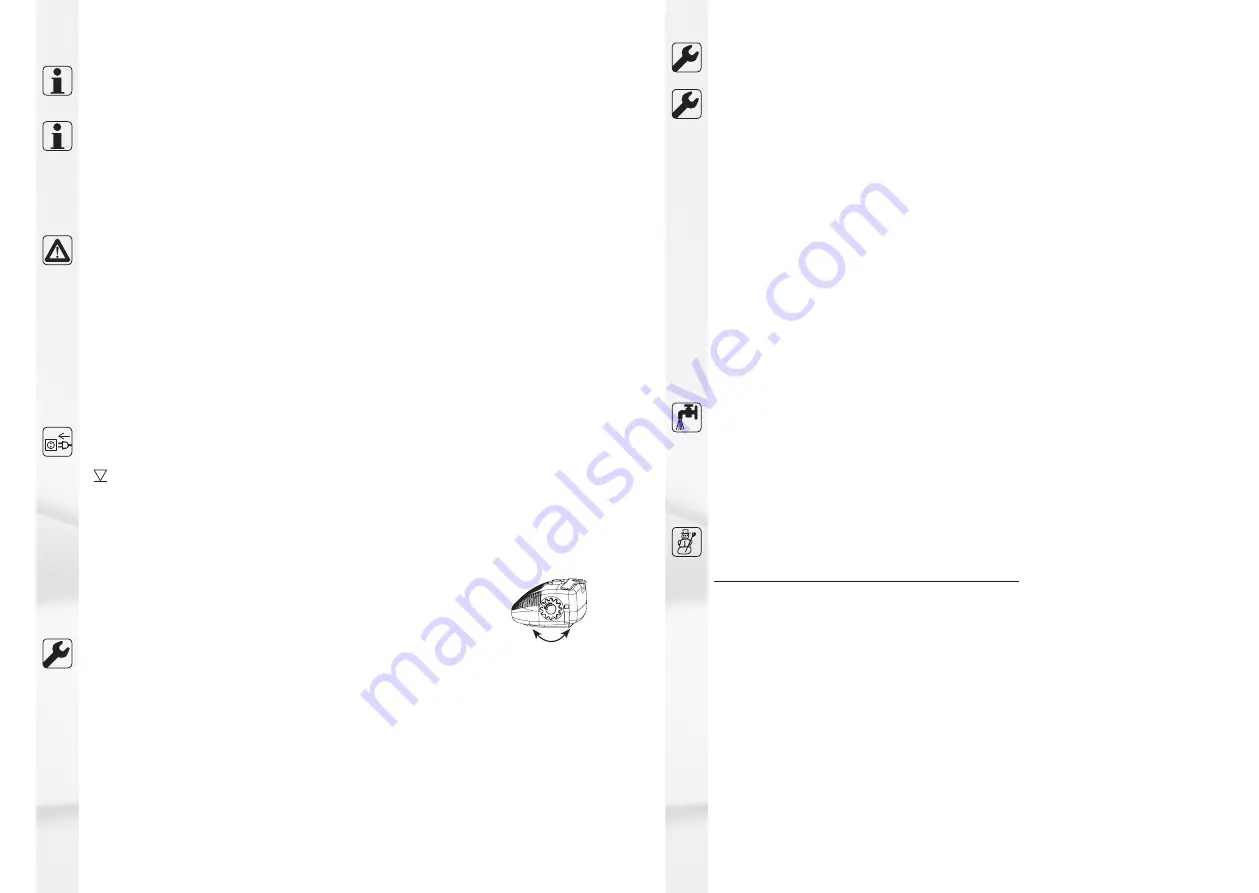
-
You can adjust the pump‘s fl ow rate (+/-) by turning the control knob (9)!
Dismantling / Assembly system-N 850 (see fi g. 2 - 5)
1. Follow the safety measures.
Disconnect the pump!
2. Push the two tabs on the back side of the pump inwards and push the upper cover (1) up and remove it.
3. Lift the entire pump (8) out of the bottom shell (2).
4. Turn the lid (4) counterclockwise through approx. 20° in the oppposite direction to the stop.
5. Remove the lid (4) from the pump (8).
6. Remove the complete rotor (6) from the pump (8).
The shaft (4.2) of the rotor (6) is mounted on two rubber
bearings (4.3) in the pump (8) and in the lid (4).
7. The complete rotor (6) can be made to rotate on the shaft (4.2).
8. Clean all parts using clear water so that they may be moved very easily. Do avoid using any sharp
instruments.
9. Re-assemble the pump as follows:
9.1. Replace complete rotor (6) in the pump (8).
Make sure the rubber bearings (4.3) are seated correctly in the pump (8) and the lid (4).
9.2. Fit turned lid (4) onto the pump (8) and turn it clockwise until stop.
9.3. Place the pump (8) into the bottom shell (2).
GB
+
-
9.4. Set the upper cover (1) into the hook of the lower cover (2) and let the back tabs snap into place.
To ensure proper functioning, repeat the above procedure frequently, depending on clogging and working
time.
Dismantling / Assembly system-N 1200, system-N 2100 (see fi g. 2, 3, 6 + 7)
1. Follow the safety measures.
Disconnect the pump!
2. Push the two tabs on the back side of the pump inwards and push the upper cover (1) up and remove it.
3. Lift the entire pump (8) out of the bottom shell (2).
4. Twist the intake lid (6) clockwise and pull it out of the pump (8).
5. The front bearing support (5.5) and an axial bearing washer (5.4) are situated in the inlet lid (6) or on
the axle (5.3) respectively.
6. Pull the rotor (5) out of the pump (8).
7. The complete rotor (5) can be rotated on the shaft (5.3).
8. The fl ywheel (5.2) and the magnet (5.1) can also be rotated against one another at a certain angle.
9. Thoroughly pull the axle (5.3) out of the pump (8).
10. Push the rear bearing support (5.5) including the axial bearing washer (5.4) out of the pump; you
may fi nd a pen to be helpful to accomplish this.
11. Insert this pen in the small bore at the pump‘s rear side (8) and use it in order to push the rear bea
ring support (5.5) including the axial bearing washer (5.4) out of the pump.
12. Clean all components - please use clear water only - so that they allow to be easily moved. Do not
use sharp-edged objects.
13. Proceed as follows in order to reassemble the pump:
13.1. Put the rear bearing support (5.5) including the axial bearing washer (5.4) onto the axle (5.3) and
insert it in the pump (8).
13.2. Put the rotor (5) onto the axle (5.3).
13.3. Put the front bearing support (5.5) including the axial bearing washer (5.4) onto the axle (5.3).
13.4. Twist the intake lid (6), insert it into the pump (8) and turn it counter-clockwise up to its stop.
13.5. Place the pump (8) into the bottom shell (2).
13.6. Set the upper cover (1) into the hook of the lower cover (2) and let the back tabs snap into place.
To ensure proper functioning, repeat the above procedure frequently, depending on clogging and working
time.
Maintenance
In order to prolong the service life of your pump and to keep it in good operating condition, it is
recommended to carry out maintenance and cleanup regularly. This can be done by everyone, quickly and
easily.
See „Dismantling/Assembly“
Servicing intervals
- In the beginning check performance of your pump every day. If necessary, clean the fi lters.
- Since servicing intervals (complete cleanup) will vary depending on pond pollution, repeat the periodic
service to your pump in accordance with the requirements given.
Should you determine that there are
damaged or worn parts
, do replace them. See „Spare parts“.
Winter / Pump care
Protect your pump from freezing-in!
Take the pump out of your pond in autumn.
Clean the pump completely following the outlined instructions.
During the winter months store the pump in a frost-resistant room.


