Form 43343350
-62-
Dec 2017
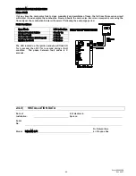
IGNITION MODULE DIAGNOSTICS
Flame Fault
If at any time the main valve fails to close completely and maintains a flame, the full time flame sense circuit
will detect it and energize the combustion blower. Should the main valve later close completely removing the
flame signal, the combustion blower will power off following the post purge period.
Fault Conditions
Error Mode
LED Indication
Internal Control Failure
Steady On
Air Flow Fault
1 Flash
Gas valve failure (stuck open)
2 Flashes
Ignition Lockout
3 Flashes
The LED located on the ignition module will flash ON
for ¼ second, then OFF for ¼ second during a fault
condition. The pause between fault codes is 3
seconds.
24.0)
INSTALLATION DATA
Date of
Installation:
# of Heaters in
System:
Serial
No.
Model: R(B,S,M) S/U
N = Natural Gas
L = Propane Gas
Summary of Contents for 44488010
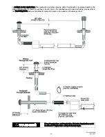
Page 15: ...Form 43343350 14 Dec 2017 7 1 TYPICAL ASSEMBLY LAYOUT STRAIGHT SERIES SHOWN ...
Page 16: ...Form 43343350 Dec 2017 15 8 0 DIMENSIONS STRAIGHT SERIES Typical Dimensions Up to 60 Ft Shown ...
Page 17: ...Form 43343350 16 Dec 2017 8 1 DIMENSIONS U SERIES Typical Dimensions Up to 50 Ft Shown ...
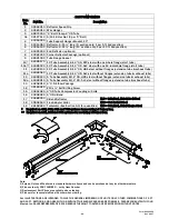
Page 18: ...Form 43343350 Dec 2017 17 8 2 HEATER ASSEMBLY JOINING OF TUBE SECTIONS ...
Page 19: ...Form 43343350 18 Dec 2017 ...
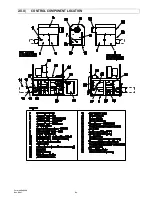
Page 52: ...Form 43343350 Dec 2017 51 20 0 CONTROL COMPONENT LOCATION ...
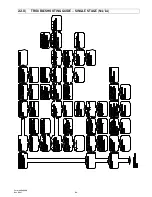
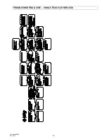
Page 54: ...Form 43343350 Dec 2017 53 22 0 TROUBLESHOOTING GUIDE SINGLE STAGE N1 L1 ...
Page 55: ...Form 43343350 54 Dec 2017 TROUBLESHOOTING GUIDE SINGLE STAGE CONTINUED ...
Page 56: ...Form 43343350 Dec 2017 55 TROUBLESHOOTING GUIDE SINGLE STAGE CONTINUED ...
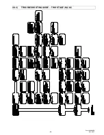
Page 57: ...Form 43343350 56 Dec 2017 22 1 TROUBLESHOOTING GUIDE TWO STAGE N2 L2 ...
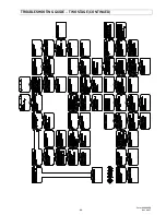
Page 58: ...Form 43343350 Dec 2017 57 TROUBLESHOOTING GUIDE TWO STAGE CONTINUED ...
Page 59: ...Form 43343350 58 Dec 2017 TROUBLESHOOTING GUIDE TWO STAGE CONTINUED ...
Page 66: ...Form 43343350 Dec 2017 65 ...

