Form 43343350
-64-
Dec 2017
15
42700500
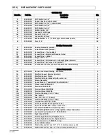
Burner, Investment Casting - Machined
1
34
43563040
Supply Cord Set (SVT-1 18/3 x 72" long) – includes connector & nut
1
35
42709000
Shield, Terminal Block
1
36
42395010
Gasket, Blower
1
37
03946010
Sealing Strip 1/8" x 3/8" wide (access panels) -not shown-
Ft.
38
42752250
Air Inlet Screen
1
38a
30504040
Starting Collar (combustion air inlet)
1
39
30701240
Ignition Cable - Female (2) 1/4" QC x 24"lg #PSE-GF23 -not shown-
1
40
44145060
Manifold Pipe – 6-1/4”lg
1
40a
03333140
Pipe Nipple – 4”lg
1
41a
44010370
Kit, Gas Valve – WR #36J23-203B1 Single Stage (natural gas)
1
41b
44010380
Kit, Gas Valve – WR #36J23-204B1 Single Stage (propane gas)
1
41c
44010390
Kit, Gas Valve – WR #36J58-201B1 Two Stage (natural gas)
1
41d
44010400
Kit, Gas Valve – WR #36J58-202B1 Two Stage (propane gas)
1
43
03259xxx
Main Burner Orifice #7/16-27 (see size requirements in Section5.0)
1
44
42741150
Air Restrictor Plate 2-3/4” (earlier models only)
1
45
44151010
Burner Screen Sub-Assembly (200 BTU units only)
1
46
42398030
Monitoring Light – Amber (gas valve operation) – 2 each for Two Stage
1
47
42398150
Monitoring Light – Red (air switch operation)
1
48
30186250
Air Switch (set point @ .93”WC, RED LABEL) 040/050 mbh
1
48a
30186260
Air Switch (set point @ .65”WC, BLUE LABEL) 075/100 mbh
1
48b
30186270
Air Switch (set point @ .34”WC, GREEN LABEL) 125/150/175/ 200 mbh
1
Labels/Manual
49
42848220
Label, Nameplate - Sterling 1-Stage
1
49a
42848221
Label, Nameplate – Mestek 1-Stage
1
49b
42848222
Label, Nameplate – Beacon 1-Stage
1
49c
42848230
Label, Nameplate - Sterling 2-Stage
1
49d
42848231
Label, Nameplate – Mestek 2-Stage
1
49e
42848232
Label, Nameplate – Beacon 2-Stage
1
50
42013070
Label,Logo – Sterling (Not Shown)
1
50a
42013080
Label,Logo – Mestek (Not Shown)
1
50b
42013090
Label,Logo – Beacon (Not Shown)
1
51
43344180
Label, Clearances to Combustibles
1
52
42874020
Label, Wire Connection Diagram 1-stage
1
52a
42874030
Label, Wire Connection Diagram 2-stage
1
54
42875000
Label, Warning (installation/configuration/chemical)
1
55
43269010
Label, 24V Thermostat Connection 1-stage
1
55a
43269060
Label, 24V Thermostat Connection 2-stage
1
56
43269020
Label, TISS Connection
1
57
43269030
Label, Eyebolt Suspension Warning
1
58
43269040
Label, Gas Valve in “OFF” Position
1
59
43269050
Label, Burner Warning (access panel must remain closed)
2
60
43344110
Label, Flex Gas Connector
1
61
42785020
Label, Ladder Wiring Connection 1-stage
1
61a
42785010
Label, Ladder Wiring Connection 2-stage
1
62
42834000
Label, 120V Caution
1
63
42922030
Label, Sidewall Venting
1
64
43269070
Label, Low/High Fire (2-stage only)
1
65
43343350
Installation & Operation Manual (Not Shown)
1
Tube Integrity Safety Switch (TISS) Components
65
44175000
Retainer clamp
1
66
30519020
Spring
1
67
30736000
Thimble
1
68
44176510
TISS replacement assembly (does not include retainer clamp or spring)
1
Summary of Contents for 44488010
Page 15: ...Form 43343350 14 Dec 2017 7 1 TYPICAL ASSEMBLY LAYOUT STRAIGHT SERIES SHOWN ...
Page 16: ...Form 43343350 Dec 2017 15 8 0 DIMENSIONS STRAIGHT SERIES Typical Dimensions Up to 60 Ft Shown ...
Page 17: ...Form 43343350 16 Dec 2017 8 1 DIMENSIONS U SERIES Typical Dimensions Up to 50 Ft Shown ...
Page 18: ...Form 43343350 Dec 2017 17 8 2 HEATER ASSEMBLY JOINING OF TUBE SECTIONS ...
Page 19: ...Form 43343350 18 Dec 2017 ...
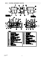
Page 52: ...Form 43343350 Dec 2017 51 20 0 CONTROL COMPONENT LOCATION ...
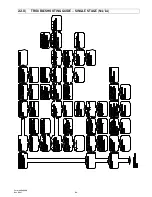
Page 54: ...Form 43343350 Dec 2017 53 22 0 TROUBLESHOOTING GUIDE SINGLE STAGE N1 L1 ...
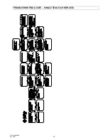
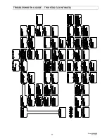
Page 55: ...Form 43343350 54 Dec 2017 TROUBLESHOOTING GUIDE SINGLE STAGE CONTINUED ...
Page 56: ...Form 43343350 Dec 2017 55 TROUBLESHOOTING GUIDE SINGLE STAGE CONTINUED ...
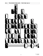
Page 57: ...Form 43343350 56 Dec 2017 22 1 TROUBLESHOOTING GUIDE TWO STAGE N2 L2 ...
Page 58: ...Form 43343350 Dec 2017 57 TROUBLESHOOTING GUIDE TWO STAGE CONTINUED ...
Page 59: ...Form 43343350 58 Dec 2017 TROUBLESHOOTING GUIDE TWO STAGE CONTINUED ...
Page 66: ...Form 43343350 Dec 2017 65 ...


