background image

Form 44201460 

Mar 2019 


 SAFETY REQUIREMENTS 


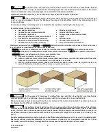
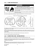
The heater area must be kept clear and free from combustible materials, gasoline and other flammable vapors 
and liquids. 


This  heater  is  designed  for  use  with  one  type  of  gas  (LPG  or  Natural).    Make  sure  that  the  type  of  gas  to  be 
supplied to this heater matches that shown on the heater rating plate. 


DO NOT install this heater directly onto an LPG container or propane cylinder.  LPG containers (propane cylinders) 
must not be stored indoors or in the vicinity of any gas-burning appliance. 


DO NOT Store flammable materials near the heater. 


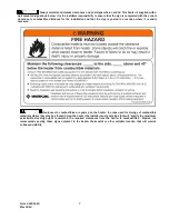
DO  NOT  locate  gas  and  electric  supply  lines  directly  above  the  heaters  path  of  flue  products.  The  path  of  flue 
products will change if an optional low clearance heat shield is installed. 


Children and adults should be alerted to the hazards of high surface temperatures and should stay away to avoid 
burns or clothing ignition. 


Young Children should be carefully supervised when they are in the area of the heater. 


DO NOT spray aerosols or flammable materials in the vicinity of this appliance while it is in operation. 


Clothing or other flammable materials should not be hung from the heater or placed on or near the heater. 


NEVER attempt to service the heater while it is plugged in, operating or hot.   


Any  guard  or  other  protective  device  removed  for  servicing  a  heater  must  be  replaced  prior  to  operating  the 
heater. 


DO NOT Install the heater in a recess, alcove or enclosure. 


Installation  and  repair  should  be  done  by  a  licensed  contractor  qualified  in  the  installation  and  service  of  gas 
heating equipment. The heater should be inspected before use and at least annually by a qualified service person.  
More  frequent  cleaning  may  be  required  as  necessary.    It  is  imperative  that  the  control  compartment,  air 
passageways and burner of the heater be kept clean. 


If any changes are made to the patio or building structure after the heaters are installed such as adding plastic 
curtains  to  enclose  the  patio  the  modified  design  must  be  checked  by  a  qualified  person  to  ensure  that  the 
clearance combustibles and ventilation requirements are maintained. 


DO NOT paint any surface of the heater. 


DO NOT throw objects at the heater. 


Avoid  inhaling  fumes  emitted  from  the  heater’s  first  use.  Smoke  and  odor  from  the  burning  of  oils  used  in 
manufacturing will appear. Both the smoke and odor will dissipate after approximately 30 minutes. 

INSTALLATION REQUIREMENTS 
Installation of this heater must conform with local building codes or, in the absence of local codes, with the National 
Fuel Gas Code, ANSI Z223.1/NFPA 54, or the Natural Gas and Propane Installation Code, CSA B149.1 In Canada, the 
installation must conform to current CSA B149.1 (The Natural Gas and Propane Installation Code) in the absence of 
local codes.  Heaters shall be installed by a licensed contractor or licensed installer.   Clearances to combustibles as 
outlined in this manual should always be observed.  In areas used for storage of combustible materials where they 
may be stacked below the heater, NFPA54 requires that the installer must post signs that will “specify the maximum 
permissible stacking height to maintain the required clearances from the heater to combustibles.” 
 
Every heater shall be located with respect to building construction and other equipment so as to permit access to the 
heater. Each installer shall use quality installation practices when locating the heater and must give consideration to 
clearances  to  combustible  materials,  vehicles  parked  below,  lights,  overhead  doors,  storage  areas  with  stacked 
materials,  sprinkler  heads,  gas  and  electrical  lines,  and  any  other  possible  obstructions  or  hazards.    Consideration 
also must be given to service accessibility. 
 

Summary of Contents for 44625000

Page 1: ...and understood before installing operating or servicing this heater Make certain to follow the Clearances to Combustibles Section 4 This heater is intended for use with either Natural Gas or Propane G...

Page 2: ...L CONNECTION WIRING DIAGRAM 29 16 1 FIELD CONNECTIONS AND WIRING DIAGRAMS 2 STAGE 29 16 2 FIELD CONNECTIONS AND WIRING DIAGRAMS SINGLE STAGE 24V 31 16 3 FIELD CONNECTIONS AND WIRING DIAGRAMS SINGLE ST...

Page 3: ...heater must be supported by materials having a working load limit of at least 115 lbs To install the heater in an adequate free area to allow the products of combustion to freely escape from the heat...

Page 4: ...he control compartment air passageways and burner of the heater be kept clean If any changes are made to the patio or building structure after the heaters are installed such as adding plastic curtains...

Page 5: ...ust be installed in accordance with ANSI NFPA 409 latest edition Standard for Aircraft Hangars ANSI NFPA 88a latest edition Standard for Parking Structures and ANSI NFPA 88b latest edition Standard fo...

Page 6: ...ustibles are defined as a surface temperature of 117 F above ambient temperature OUTDOOR Spaces are defined as a shelter no more inclusive than a with walls on all sides but with no overhead cover b w...

Page 7: ...the sign is posted in a location where it is easily accessed Clearances to combustibles are posted on the heater In areas used for storage of combustible materials where they may be stacked below the...

Page 8: ...siding canvas tri ply etc may be subject to degradation at lower temperatures It is the installer s responsibility to assure that adjacent materials are protected from degradation See below the possib...

Page 9: ...siding canvas tri ply etc may be subject to degradation at lower temperatures It is the installer s responsibility to assure that adjacent materials are protected from degradation See below the possi...

Page 10: ...Electrical Supply Current Rating Weight Natural or Propane NPT Male 120 Volt 60Hz 1 Phase 0 1 Amp 55 lbs Module Electrical Rating Ignition System direct spark Input Control 18 30 VAC 50 60 Hz class 2...

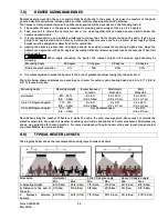
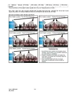
Page 11: ...60 degree Radiant output reduction 3 13 29 50 5 It is recommended to place the heaters in the area of greatest heat loss facing into the patio area The table below shows minimum area coverage per heat...

Page 12: ...stance D for angled heaters applies when they are facing towards each other Note Local codes may have special requirements regarding head clearance requirements Some local codes require all portions o...

Page 13: ...optional accessories available for the Wind Blocker Patio heater PN Description Picture 44560350 Wall Ceiling Telescopic Mounting Bracket Kit 15 22 overhead space check clearances to combustibles spac...

Page 14: ...Mount Bracket Kit 10 fixed installation for minimum overhead clearance This bracket is only for horizontal mounting with the heat shield 44566300 Heat Shield Kit Reduced clearances to combustible opti...

Page 15: ...Care must be taken when up packing the heater Carefully open the top of the heater as indicated on the labels at the side of the shipping box An angle gauge is attached to the heater s control side wi...

Page 16: ...pan between supporting beams f The appliance should be located with respect to building construction and other equipment to permit access to the appliance for servicing etc f The heater must be instal...

Page 17: ...er angle if needed Note If a heat shield is installed its location must match the heaters angle see Section 21 0 This process must be repeated for both ends of the heater INDOOR INSTALLATION HANGING M...

Page 18: ...range of lengths and approved mounting angles of 150 300 450 and 600 44560350 KIT BRACKET WALL CEILING 15 22 CEILING FOR USE WITH HEAT SHIELD telescoping 44560351 KIT BRACKET CEILING 22 30 FOR USE WI...

Page 19: ...angle and whether a heat shield is installed 15 22 Bracket With heat shield telescope hole positions 22 30 Bracket Without heat shield telescope hole positions Mounting Angle INDOOR OUTDOOR INDOOR OUT...

Page 20: ...inimum working load of 115lbs 12 3 2 HEATER ATTACHMENT TO HANGING BRACKETS The heater can be attached to the hanging brackets in angles of 150 300 450 and 600 Choose the desired heater mounting angle...

Page 21: ...UT 2 4 02352000 PHSMS 8 x 1 2 AB POINT SS BLK OXIDE 8 5 44568139 RAIL HEAT SHIELD HANGER PAINTED 1 6 44566189 HEAT SHIELD ROLLED PAINTED 1 7 44568149 HOLDER BRACKET PAINTED 2 8 43247112 LABEL INDOOR C...

Page 22: ...eld hanger rail to the holder bracket using 2 black oxide 8 screws on each end Horizontal position shown below IMPORTANT Use the Acorn nuts at the control end of the heater as shown in the illustratio...

Page 23: ...ERAMIC GLASS 14 0 Only install the ceramic glass once the heater has been attached to a suitable gas see Section 15 0 electrical supply see Section 16 0 and has been commissioned see Section 18 0 Read...

Page 24: ...der the Glass Retainer at the heaters control enclosure side At this point the glass will be flush with the heater at the insertion point Note If the ceramic glass does not slide in easily review posi...

Page 25: ...of the heater h The gas pipe flexible hose and connections must be self supporting The gas pipe work must not bear any of the weight of the heater or any other suspended assembly i This appliance is e...

Page 26: ...UCTIONS FOR PRESSURE TEST GAUGE CONNECTION 15 1 INLET GAS PRESSURE CHECK 15 2 1 The installer will provide a 1 8 N P T tapped plug accessible for test gauge connection immediately upstream of the gas...

Page 27: ...e solenoid Do not energize the HI solenoid 2 Remove regulator cover screw from the low outlet pressure regulator see Figure 1 below and turn screw clockwise to increase pressure or counterclockwise to...

Page 28: ...r shall be connected to a permanently live electrical circuit one that is not controlled by a light switch 4 The power supply to the unit should be protected with a fused disconnect switch or circuit...

Page 29: ...below shows the internal wiring diagram of the heater and the optional external connections depending on how the heater will be controlled FIELD CONNECTIONS AND WIRING DIAGRAMS 2 STAGE 24V 16 2 The f...

Page 30: ...44201460 30 Mar 2019 A LOW VOLTAGE 24V 3 POSITION SWITCH CONNECTIONS SINGLE HEATERS B LOW VOLTAGE 24V 3 POSITION SWITCH CONNECTIONS MULTIPLE HEATERS C LOW VOLTAGE 24V THERMOSTAT CONNECTIONS SINGLE HEA...

Page 31: ...The figure below shows the internal connection to operate the heater turning on and off 24V power to the heater with a permanent live power supply Important To operate the heater as single stage a jum...

Page 32: ...GLE STAGE 120V 16 4 The figure below shows the internal connection to operate the heater turning on and off 120V power to the heater Important To operate the heater as single stage with 120V all three...

Page 33: ...d and the minimum vent flow required is as follows WB35 N2and L2 140 cfm The General Ventilation Rules outlined in ASHRAE GUIDE AND DATA BOOK should be observed when locating vents Exhaust vents must...

Page 34: ...occurs after successful ignition the appliance will attempt one re ignition before going to Lockout conditions 9 To shut down the appliance for short periods of time switch off the electrical supply t...

Page 35: ...door Clearances to Combustibles Check that the area has not been closed in making it an indoor installation If any changes have been made then the clearances and ventilation requirements for Indoor in...

Page 36: ...rt or debris including spider webs Foreign Objects Check and remove any foreign objects that are logged between the heat shield and the heater Ceramic Glass Clean the glass from the inside and outside...

Page 37: ...Form 44201460 37 Mar 2019...

Page 38: ...logo emblem s final position to be at the control side of the heater 4 2 Slide the glass into the Glass Retainer Rails The glass must be held parallel to the Glass Retainer Rails during assembly The...

Page 39: ...Remove any foreign matter from the electrode tips and check that the spark gap is 199 5mm If the electrode flame sensor rods are badly oxidized replace the electrode flame sensor in the reverse order...

Page 40: ...is removed from the illustration for clarity Loosen the panel nut 1 using a 19mm end wrench and remove from the gas valve manifold 2 Disconnect the wires to the gas valve 3 Remove the 4 screws from t...

Page 41: ...e it from the heater 3 Disconnect the transformer lead wires Remove the screws 3 holding the transformer and remove it from the heater REMOVAL OF MAIN BURNER EMITTER ASSEMBLY 21 6 A Remove the ceramic...

Page 42: ...Form 44201460 42 Mar 2019 INSTALLATION DATA 22 0 Date of Installation Number of Heaters in System Heater Serial Number Heater Model R B S W35 N Natural Gas L Propane Gas...

Page 43: ...Module Fenwal 35 602906 915 1 Burner and Frame Components 1g 02132060 Rivet 1 8 x 294 SS grip range 188 250 not shown 10 1c 02168050 PHMS 10 24 x 3 8 SS 6 15 44555100 Support Plate Venturi 1 16 44570...

Page 44: ...Please order by Part Number not by Item Number Refer to complete Model Number when ordering All replacement parts prices are available when ordering MODEL NUMBER SUFFIXES N2 Natural Gas L2 Propane Gas...

Page 45: ......

Reviews: