background image

5-5

Operating and Maintenance Manual

Installation

code 5040275001 Rev. September 2010

Attention: the equipment’s neutral passes through.

WARNING

The neutral conductor cable of the mains input must ALWAYS be connected! If the neutral 

is not connected the UPS could be seriously damaged when powered off the mains.

BYPASS GRID CONNECTION:

The connection of a separate bypass line is only possible if the neutral conductor of the bypass 
line and that of the mains input are in common (the same potential). The neutral of the UPS’s 
mains input, bypass input and through output are connected together internally.
Before connecting the bypass line, check that the available mains power is higher or the same 
as the UPS’s rated input power. Also check that the cables to connect to the UPS are discon-
nected upstream and there is no voltage. 
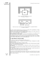
• Connect the earth cable to its terminal on the base of the equipment.
• Remove the three jumpers between mains input and bypass input which are between phases 
L1, L2 and L3 of their disconnectors.
• Connect the neutral bypass line cable to its terminal on the bypass input disconnector using 
a suitable cable terminal.
• Connect cables L1,L2 and L3 and neutral of the bypass input line to their terminals on the 
bypass input disconnector using suitable cable terminals and taking care to observe correct 
cyclicity of the phases L1, L2 and L3.
Connect cables L1,L2 and L3 and neutral of the bypass line from the low voltage distribution 
panel to their terminals on the bypass input disconnector using suitable cable terminals and 
taking care to observe correct cyclicity of the phases L1, L2 and L3.

Note: the UPS is factory supplied with the bypass input in common with the mains input.

WARNING

The neutral conductor cable of the bypass line must ALWAYS be connected! If the neutral is 

not connected the UPS could be seriously damaged when powered off the mains.

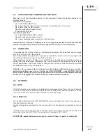
5.2.8 Wiring

An opening in the base of the UPS is for passing the cables through and there are also some 
fixing points for the cables. It is essential to secure the cables firmly after they have been con-
nected to the equipment.

Summary of Contents for ARCHIMOD 100

Page 1: ...ARCHIMOD Operating and Maintenance Manual Rev September 2010 Code 5040275001 The original of this document is drawn up in the Italian language...

Page 2: ......

Page 3: ...Models 2 3 2 4 Technical specifications 2 6 2 5 Communication devices 2 11 2 5 1 RS232 serial ports 2 11 2 5 2 Relay interface 2 11 2 5 3 Logic level interface 2 12 2 5 4 Communications slot 2 13 3 S...

Page 4: ...1 6 1 Input configuration 6 1 6 2 Output configuration 6 1 6 3 Checks prior to switching on 6 2 6 4 Starting procedure 6 2 7 CONTROL PANEL 7 1 7 1 Service Mode function 7 2 7 2 Main menu and submenus...

Page 5: ...ntenance Manual code 5040275001 Rev September 2010 10 DISMANTLING 10 1 10 1 Disposing of the batteries 10 1 10 2 Dismantling the UPS 10 1 10 3 Disposing of the electronic components 10 1 11 TABLES 11...

Page 6: ...ajakovskij 10 b Reggio Emilia Italy Type of equipment UPS Models Year in which trademark was affixed The device was tested in the typical installation configuration and with peripherals conforming to...

Page 7: ...ion simply defined manual herein contains all the information for the installation use and maintenance of the equipment specified in the Declaration of Conformity This equipment will be referred to si...

Page 8: ...n work that exist in the country where the equipment is installed Reference is also made in this manual to laws directives etc that the user must know and consult in order to fulfil the purposes estab...

Page 9: ...rer the user must scrupulously comply with the precautions indicated in the manual and in particular to always work within the equipment s limits of use to always carry out constant and accurate maint...

Page 10: ...recommended by Meta System S p A because it is possible and reasonable to foresee that an anomaly or malfunction of the product can cause an anomaly in the life support device or significantly comprom...

Page 11: ...ent of the power modules is also possible turning the control off as well as the set of modules connected to it without having to power the load from the bypass line thus temporarily losing protection...

Page 12: ...n can be easily pulled out and put inside the cabinet In order to guarantee maximum safety especially during maintenance the voltage of each box is adequately disconnected into two 36 and 48V that are...

Page 13: ...2 3 Operating and Maintenance Manual Technological Description code 5040275001 Rev September 2010 2 3 MODELS UPS ARCHIMOD 20 UPS ARCHIMOD 40 UPS ARCHIMOD 20 18U...

Page 14: ...2 4 Operating and Maintenance Manual Technological Description code 504275001 Rev September 2010 UPS ARCHIMOD 60 UPS ARCHIMOD 80 UPS ARCHIMOD 100...

Page 15: ...2 5 Operating and Maintenance Manual Technological Description code 5040275001 Rev September 2010 UPS ARCHIMOD 120 UPS ARCHIMOD BATTERY...

Page 16: ...ut Output nominal frequency Hz 50 60 sincronized Output connections Trifase Neutro Efficiency Mains On Line Mains Eco mode 95 99 Over load 125 for 10 min 150 for 1 min Factor crest 3 5 1 GENERAL CHARA...

Page 17: ...y 0 with 3 fhase load 66 with single fhase load 50 66 75 80 84 Power Module PM7 3 6 9 12 15 18 Nominale Power 6 7KVA Active PowerPotenza attiva 5 4KW Characteristics of Power Module PM7 Hot swappable...

Page 18: ...75001 Rev September 2010 FUNCTIONAL ELECTRICAL CHARACTERISTICS Maintenance By pass Yes Automatic by pass Yes Expendable Yes power modules and battery drawers Redundancy Yes Restart Yes after complete...

Page 19: ...fuse 20 40 60 KVA there are internal fuses not removable by the user front panel Back Feed protection No Batteries Type of batteries 12V 7 2Ah or 12V 9Ah maintenance free sealed lead batteries KB Seri...

Page 20: ...80kVA 100kVA 120kVA 7 2Ah 10 7 4 5 12 1 Battery 9Ah 12 9 6 7 2Ah 28 20 15 24 2 Battery 9Ah 30 23 18 7 2Ah 45 33 28 36 3 Battery 9Ah 49 36 30 Hp Standard autonomies Load 100 efficiency 91 KB 20kVA 175...

Page 21: ...hole set of data on UPS operation can be accessed by means of a computer or network board besides being able to control the unmanned switching off of the operating system The second called user interf...

Page 22: ...utput active high Pin 3 Autonomy Reserve output active high Pin 4 RS232 power supply Pin 5 ON OFF input equivalent to the ON OFF key on the panel Pin 6 Input for battery test it forces the UPS to run...

Page 23: ...September 2010 2 5 4 Communication slot A slot at the back of the UPS ARCHIMOD is for the SNMP board optional Attention the maximum current taken from pin4 of connector DB15 RS232 power supply and fr...

Page 24: ...chronology described in this manual 3 2 SYMBOLS In this manual some operations are highlighted by graphical symbols that call the attention of the reader to the dangerousness of the operations The gra...

Page 25: ...be made aware of the contents of this manual 3 4 1 Qualification required to the operator The operator must follow the instructions given to ensure maximum safety for himself and for the others In par...

Page 26: ...he contents of this chapter 3 5 INDIVIDUAL PROTECTIVE GEAR WARNING There is a high risk of electrical shock with the equipment as well as a considerable short circuit current When using and servicing...

Page 27: ...rbidden to remove these plates or to work in a way different from what is indicated on them All the data on the plates must always be readable and cleaned periodically If a plate is ruined and or is n...

Page 28: ...work is being done Work underway signs must be affixed in the department that can be seen from all access points Connection of the equipment and of any accessory devices must include standard earthing...

Page 29: ...e toxic waste Under no circumstances can a battery be burnt as it would cause an explosion All maintenance work routine and extraordinary must be recorded in a register noting the date time type of jo...

Page 30: ...ete and in order when receiving it Make sure that The shipping data consignee s address number of packs order number etc are the same as those written on the accompanying documents The technical legal...

Page 31: ...will prevent or reduce visibility on the point you are working on or on the surrounding areas 4 3 POSITIONING AND UNPACKING To position and unpack the UPS please follow this procedure 1 Take the UPS t...

Page 32: ...f a suitable capacity in serting the forks in the base making sure they come through on the opposite side by at least twenty centimetres The means used for lifting must be driven at slow speed with mi...

Page 33: ...hes When the unit detects the input voltage it automatically proposes starting a battery charging cycle After about 1 minute charging starts automatically and the time left to finish charging is shown...

Page 34: ...ARCHIMOD units must be installed with a thermal circuit breaker upstream Connection of the unit to the mains using a traditional plug is not al lowed 2 A warning label must be affixed on all mains sup...

Page 35: ...voltage volt V in input and frequency correspond to the values on the UPS rating plate 2 earthing complies with the IEC standards International Electronic Commission or local regulations 3 the electr...

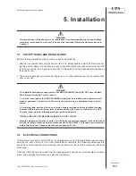
Page 36: ...WARNING The following instructions are of a prescriptive nature and it is imperative they be complied with Opening or removing the panels from the UPS ARCHIMOD or ARCHIMOD BATTERY you risk exposure t...

Page 37: ...the EARTH terminal on the UPS terminal block INDICATION The wiring diagrams are given in the DIAGRAMS chapter 5 2 7 Connecting the power supply For safety reasons connection of the power supply must...

Page 38: ...input which are between phases L1 L2 and L3 of their disconnectors Connect the neutral bypass line cable to its terminal on the bypass input disconnector using a suitable cable terminal Connect cables...

Page 39: ...d by the silk screen print see 2 5 2 If there is more than one contact interface connect the E P O terminals that are on each contact interface as follows connect the E P O terminals of the interfaces...

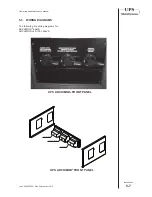
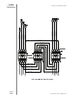
Page 40: ...code 5040275001 Rev September 2010 5 3 WIRING DIAGRAMS The following are wiring diagrams for ARCHIMOD 60kVA ARCHIMOD 80 100 120kVA INPUT INGRESSO MAINTENANCE BYPASS BYPASS MANUTENZIONE OUTPUT USCITA...

Page 41: ...5 8 Operating and Maintenance Manual Installation code 504275001 Rev September 2010 Rin Sin Tin Nin Rout Sout Tout Nout UPS ARCHIMOD FRONT PANEL...

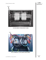
Page 42: ...5 9 Operating and Maintenance Manual Installation code 5040275001 Rev September 2010 UPS ARCHIMOD 60KVA REAR PANEL E P O E P O UPS ARCHIMOD 80 100 120KVA REAR PANEL...

Page 43: ...rminal block Therefore it is ALWAYS necessary to select the load type applied via the display The default configuration for the UPSARCHIMOD units is THREE 120 phases 400 VAC For power 20 kVA the unit...

Page 44: ...ess the ENTER key on any operator panel to gain access to the Service Mode See chapter 7 for more information about the SERVICE MODE and how the operator panel works 4 Follow this path UPS Config Outp...

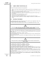
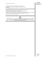
Page 45: ...harging in standby and proceed with turning the ARCHIMOD UPS on 9 Press the ON OFF button to switch the UPS on 10 Wait until the status indicator on the display turns a fixed green 11 Check that the o...

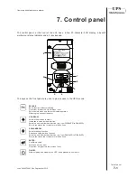
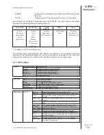
Page 46: ...Exit the main menu and return to displaying status Silencing the acoustic indicator UP ARROW Selects the previous function Increases a value inside a function Selects a new item inside a function e g...

Page 47: ...ower absorbed by the load and percentage of the total load applied Bar showing residual battery capacity and actual minutes of operation in the case of a power failure from the mains INDICATION Press...

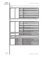
Page 48: ...rmware version inside the machine PM SW vers Firmware version of the power modules S N Machine serial number UPS config OUT Single phase Three phase IN Single phase Three phase PM Pos X X X X power mo...

Page 49: ...ent supplied by the batteries negative if the batteries are being charged A Residual Ca pac Battery charged status expressed as a percentage 0 100 Chg Status Working status of the battery charger Tot...

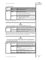
Page 50: ...with the input for frequency variations of 14 of the nominal value If disabled the UPS synchronises for variations of frequency of 2 Note the PLL function sees to it that the unit s output frequency...

Page 51: ...basis of the load applied Capacity Sets the capacity value of the batteries in the UPS Ah Available in the Service Mode only Operator Panel Language Sets the display language Keyboard Beep Enables di...

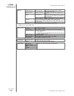
Page 52: ...he power module X by the mains A Frequency Frequency of the sinusoid voltage in input to the power module X Hz Peak I Factor Peak factor applied by the power module X to the mains Power factor Power f...

Page 53: ...No Overloads Total number of overloads No HV Bus run Total number of overvoltages on the Bus No Out DC Level Total number of continuous voltage presences in output from the PMs INDICATION Press ENTER...

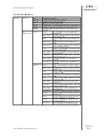
Page 54: ...our of the batteries Signalling Test Tests the luminous signals Press ENTER to carry out the test on the signals of the status indicator green orange and red and the acoustic signals LCD Display Test...

Page 55: ...275001 Rev September 2010 If you expect to leave the UPS off for a long time please read carefully and put into practice what is prescribed in paragraph 4 4 concerning storage If these operations are...

Page 56: ...uld be PLL disabled Frequencyoftheinputvoltage out of the limits foreseen by the UPS GREEN Long intermittent Bypass input KO The UPS signals that the bypass is unusable ORANGE Fast intermittent ORANGE...

Page 57: ...e batteries to check their status and that they are working properly BATTERY EQUALIS The UPS is equalising the batteries BUZZER OFF The buzzer is turned off AUTONOMY RESERVE Battery charge level is at...

Page 58: ...WN DUE TO END OF AUTONOMY Battery charge level is too low UPS in shutting down START UP WITH BATTERY FAILED Start up with battery failed MAXIMUM TIME ON BATTERY Battery autonomy finished The batteries...

Page 59: ...hutdown BATTERY CHARGER START IN STAND BY The battery charger started in standby UPS ON BATTERY UPS on battery UPS ON MAINS UPS on mains OUTPUT OFF The output is off BATTERY TEST NEXECUTED Batteries t...

Page 60: ...ect operations or activities if not carried out according to the instructions given in this manual with particular reference to the safety rules and regulations that can be found in chapter 3 To ensur...

Page 61: ...ced bypass mode WARNING It is strictly forbidden to change the power modules if first the following instructions have not been scrupulously complied with 1 Open the door of the UPS ARCHIMOD 2 Enable t...

Page 62: ...to replace and put them aside without losing them 7 Take the modules out to replace one at a time 8 Check that on all the new power modules the two LEDs that can be seen through the two holes on the c...

Page 63: ...ch 6 Turn the UPS off keeping the ON OFF button pressed for more than 2 seconds 7 Open the mains input disconnector switch 8 Open all the battery disconnectors of the UPS and of the ARCHIMOD BATTERY u...

Page 64: ...on the front panel turns green 8 Close the ARCHIMOD door 9 6 Installing replacing battery boxes There are two different ways to install replace ARCHIMOD UPS 20 40 and 60kVA and AR CHIMOD BATTERY batte...

Page 65: ...valid for all ARCHIMOD UPS and ARCHIMOD BATTERY models Attention the load is powered directly by the mains input when in the maintenance bypass mode 1 To put the UPS in the maintenance bypass mode pro...

Page 66: ...he UPS ARCHIMOD must be re moved To remove and dismantle the unit wear the Individual Protective Gear described in chapter 3 and refer to the instructions and charts that you will find in this manual...

Page 67: ...2 111 A 3 1 5 x 25 mm2 3 x 25 mm2 111 A 40 kVA 3 3 5 x 25 mm2 5 x 25 mm2 74 A 60 kVA 3 3 5 x 35 mm2 5 x 35 mm2 111 A 80 kVA 3 3 5 x 50 mm2 5 x 50 mm2 148 A 100 kVA 3 3 5 x 70 mm2 5 x 70 mm2 185 A 120...

Page 68: ...3 100A 3P N curva C 3 1 100A 1P N curva C 1 1 3 40 kVA 80A 3P N curva C 3 3 60 kVA 100A 3P N curva C 3 3 80 kVA 150A 3P N curva C 3 3 100 kVA 180A 3P N curva C 3 3 120 kVA 200A 3P N curva C 3 3 Tabel...

Page 69: ...12 1 Operating and Maintenance Manual Notes code 5040275001 Rev September 2010 12 Notes...

Page 70: ......

Page 71: ......

Page 72: ...2 308382 info metasystem it METASYSTEM spa declines all liabilities for injuries to people or damage to things caused by a use of the unit that does not conform to the information given in this manual...

Reviews: